© 2008 Trane 2 18-GE08D1-6
Installer’s Guide
Manual D, Manual S and Manual RS along with the
air handler Product Data and Service Facts for addi-
tional information.
5. The area around refrigerant lines must be sealed
and electrical inlets need to be sealed at both the
low and the high voltage.
6. It is recommended that the outline drawing be
studied and dimensions properly noted and checked
against selected installation site. By noting in ad-
vance which knockouts are to be used, proper clear-
ance allowances can be made for installation and
possible future service.
7. Allow a minimum of 21 inches clearance in
front of the air handler to permit service and re-
moval of filter.
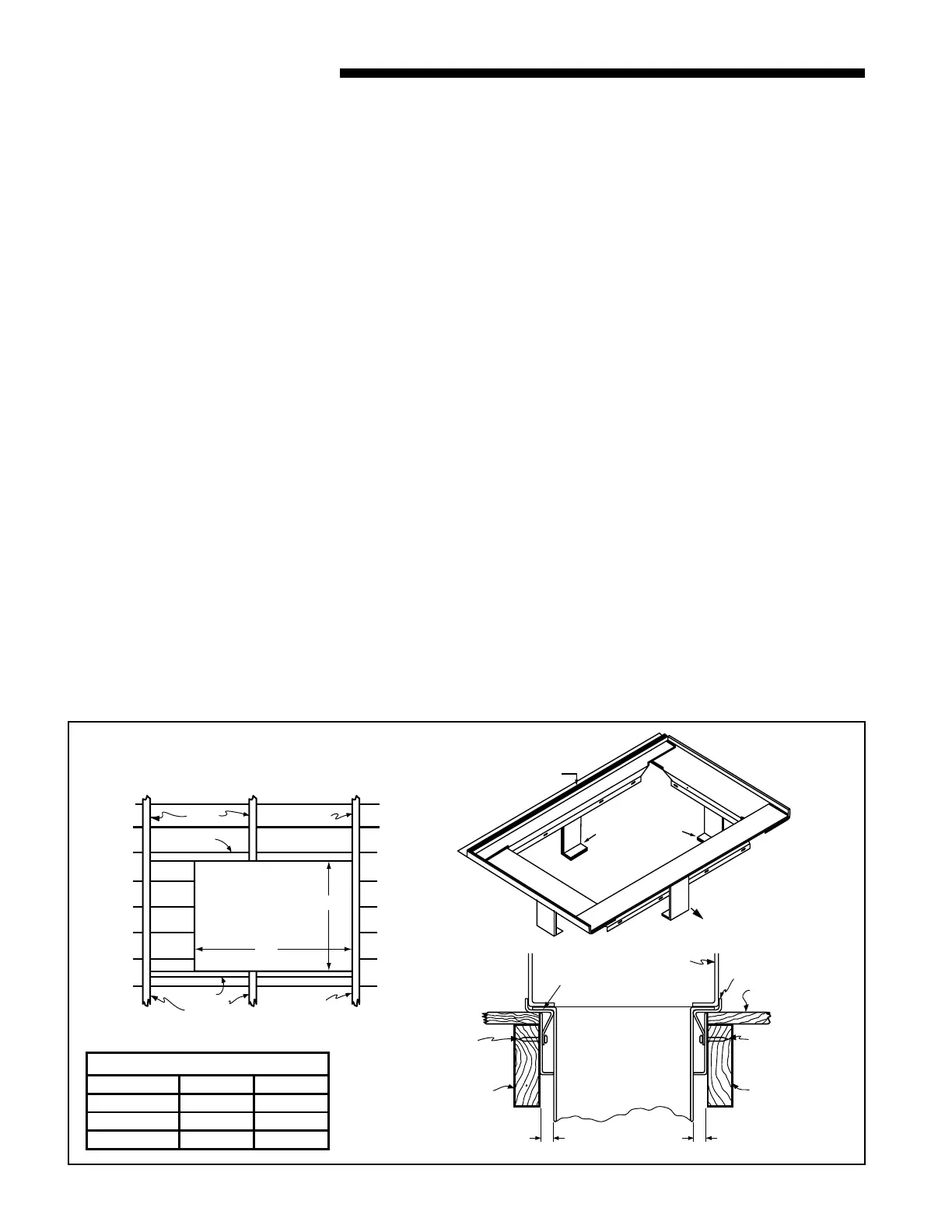
8. When air handler with supplementary heater is to
be installed in the downflow position on combus-
tible flooring an accessory subbase (TAYBASE101
for 2TEC3F18-36B, TAYBASE102 for 2TEC3F55 and
TAYBASE100 for 2TEC3F42B-60B) must be used.
See Figure 1.
9. If supplementary heat is to be added, power supply
must be sufficient to carry the load. In addition,
minimum air flow settings, unit and duct clearances
to combustible material must be maintained as
stated on the air handler rating nameplate.
These air handlers are suitable for installation in a
closet, alcove or utility room with free, non-ducted, air
return, using the area space as a return air plenum.
With ducted supply air, if the minimum clearances to
combustible materials and service access are observed,
the above installations are suitable.
This area may also be used for other purposes, includ-
ing an electric hot water heater – but in no case shall
a fossil fuel device be installed and/or operated in
the same closet, alcove or utility room.
In addition, these air handlers are suitable for installa-
tion in an attic, garage or crawl space with ducted sup-
ply and return air.
This equipment has been evaluated in accordance with
the Code of Federal Regulations, Chapter XX, Part 3280
or the equivalent. “SUITABLE FOR MOBILE HOME
USE.”
For proper installation the following items must be con-
sidered:
1. If adequate power is available and correct according
to nameplate specifications.
2. Insulate all ducts, particularly if unit is located out-
side of the conditioned space.
3. Pursuant to Florida Building Code 13-610.2.A.2.1,
this unit meets the criteria for a factory sealed
air handler.
4. To ensure maximum efficiency and system perfor-
mance, the existing supply and return duct system
static pressures must not exceed the total available
static pressure of the air handler. Reference ACCA
B
A
JOIST
JOIST
JOISTS
HEADER
JOISTS
HEADER
NAILS
REAR
FLANGE
FRONT OF
UNIT
HEADER
1"
NAILS
HEADER
MIN. SPACING TO
ANY COMBUSTIBLE
MATERIAL.
1"
APPROX. 3/4" FLANGES ON FIELD
FABRICATED DUCT OR PLENUM
ONE INCH DUCT SPACERS
FLOOR
SUBBASE
UNIT
AIR HANDLER SUBBASE
1
FLOOR OPENING - SIZE
MODEL NO. A B
TAYBASE100 23-3/4 14-13/16
TAYBASE101 21-3/4 14-13/16
TAYBASE102 26-3/4 14-13/16

 Loading...
