18-GE08D1-7 7
Installer’s Guide
j. No sheetmetal screws may be used to attach re-
turn ductwork on the side of the unit.
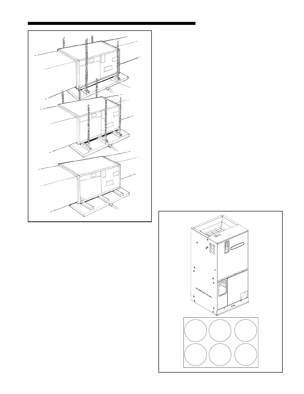
k. Openings where field wiring enters the
cabinet must be completely sealed. Location
of power entry is shown on the outline drawing.
Use 2.5" clear stickers provided to seal all unused
electrical knockouts. See Figure 11.
l. After ductwork connections are made, seal air-
tight and per Local codes.
HORIZONTAL RIGHT
a. For maximum efficiency and Customer ease of
filter maintenance, it is recommended that a
properly sized remote filter grille be installed
for horizontal applications. Airflow should not ex-
ceed the face velocity of the filter being used.
The factory installed filter should then be
removed from the unit.
b. Unit is shipped from the factory in the upflow or
horizontal right configuration. Unit conversion is
not required.
c. If the unit is suspended, it must be supported
from the bottom near both ends as well as the
middle to prevent sagging. The service access
must remain unobstructed. If the unit is sup-
ported along the length of the front and back
with rails, the air handler only needs to be sus-
pended at both ends. See Figure 10.
with rails, the air handler only needs to be sus-
pended at both ends. See Figure 10.
If the unit is not suspended it must be supported
as mentioned above and isolated carefully to pre-
vent sound transmission. Vibration isolators (pur-
chased locally) must be placed under the unit.
e. It is always recommended that an auxiliary drain
pan be installed under a horizontal air handler
(See Condensate Piping) to prevent possible dam-
age to ceilings.
f. Isolate the auxiliary drain pan from the unit or
from the structure.
g. Connect the auxiliary drain line to a separate
drain line (no trap is needed in this line) and ter-
minate according to National and Local codes.
h. If a return duct is connected to the air handler, it
must be the same dimensions as the return
opening shown in the outline drawing.
i. On units with sheetmetal returns: Return ple-
num should be flanged. Sheetmetal screws must
be 1/2" in length or shorter.
Rail
0
Electrical Knockout Sticker Sheet
q

 Loading...
