6 18-GE08D1-7
Installer’s Guide
k. If a return duct is connected to the air handler, it
must be the same dimensions as the return
opening shown in the outline drawing.
l. On units with sheet metal returns: Return
plenum should be flanged. Sheetmetal screws
must be 1/2" in length or shorter.
m. No sheetmetal screws may be used to attach
return ductwork on the side of the unit.
n. Openings where field wiring enters the cabi-
net must be completely sealed. Location of
power entry is shown on the outline drawing.
Use 2.5" clear stickers to seal all unused electri-
cal knockouts. See Figure 11.
o. After ductwork connections are made, seal air-
tight and per local codes.
HORIZONTAL LEFT
a. To convert the unit to horizontal left, front ac-
cess, slide the coil out on the coil channel sup-
ports and rotate the complete coil 180 degrees.
b. For maximum efficiency and Customer ease of
filter maintenance, it is recommended that a
properly sized remote filter grille be installed
for horizontal applications. Airflow should not ex-
ceed the face velocity of the filter being used.
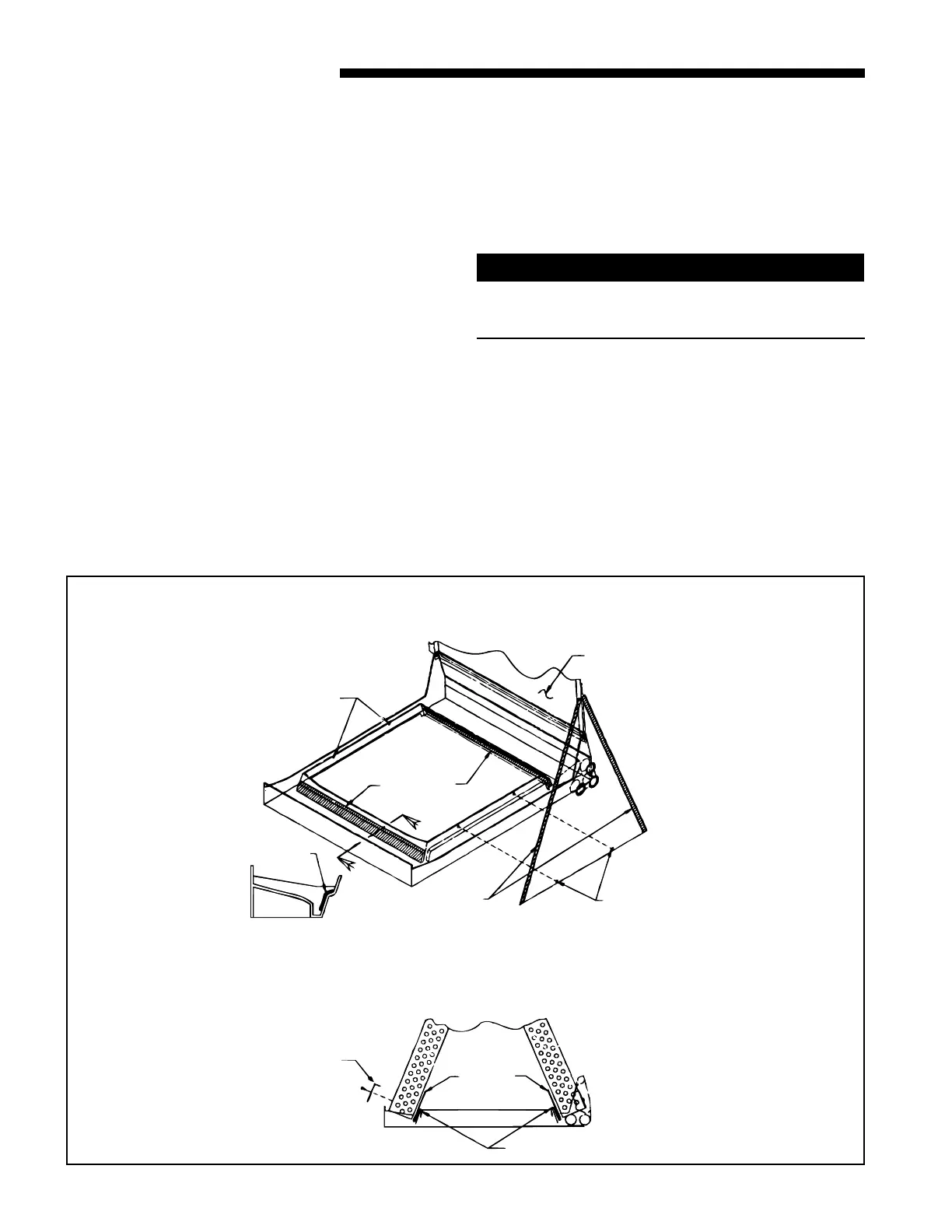
The factory installed filter should then be
removed from the unit. Remove the factory
installed baffle assembly from the apex of the coil
by using a 5/16" nutdriver to remove the hex
head screws. Replace this baffle with the factory
supplied narrow coil baffle using the screws re-
moved previously. See Figure 5.
CAUTION
!
When installing the narrow coil baffle, make sure to
align the baffle up with the holes so NOT to puncture
the coil tubing.
c. The coil is then inserted back into the cabinet on
the opposite side coil channel supports. The unit
is now horizontal left with front access. Do not
reattach coil support tab.
d . If the unit is suspended, it must be supported
from the bottom near both ends as well as the
middle to prevent sagging. The service access
must remain unobstructed. If the unit is sup-
ported along the length of the front and back
DOWNFLOW BAFFLE KIT
X
X
7/8" GASKET
SCREWS TO
REMOVE COIL
SCREWS TO
REMOVE COIL
DISCARD HORIZONTAL
DRIP TRAY
1/2" GASKET
INSIDE SURFACE
OF BAFFLE
7/8" GASKET
SECT. X-X
(TYP. BOTH SIDES)
FILL WITH SEALANT
WATER
BLOW-OFF
BAFFLES
ATTACH WITH
2 SCREWS
EACH SIDE
WATER
DIVERTER
BAFFLES
(5TON ONLY)
9

 Loading...
