18-GE08D1-6 5
Installer’s Guide
the coil. Remove drip tray by gently breaking
the seal between the drip tray and drain pan.
b. Remove the factory installed baffle assembly
from the apex of the coil by using a 5/16"
nutdriver to remove the screws. Replace this
baffle with the factory supplied narrow coil
baffle using the screws removed previously
(See Figure 5).
CAUTION
!
When installing the narrow coil baffle, make sure to
align the baffle up with the holes so NOT to puncture
the coil tubing.
NOTE: INSTALLATION OF THE DOWNFLOW BAFFLE
KIT INCLUDED WITH UNIT IS REQUIRED ON
DOWNFLOW APPLICATIONS. SEE FIGURE 9.
c. Remove front shield by removing screws on right
side. Make sure to reinstall front shield after
baffle changes. See Figure 9.
d. Detach the coil from the drain pan by removing 4
screws as shown in Figure 9.
e. Remove the front triangular baffle from the coil
and install the 1/2" wide gasket provided per
Figure 9. Trim the gasket length to fit the baffle.
Reinstall the baffle to coil, with gasket material
compressed against the coil.
f. Install the water blow-off baffles provided on each
side of the coil with the flange at the top as
shown in Figure 9. The bottom of the baffle is to
be as close to the bottom of the coil as possible.
g. Install the 7/8" wide gasket in each side of the
drain pan as shown in Figure 9.
h. Place the 2 water diverter baffles (5 ton model
only) underneath the coil on the inside edge of
the drain pan, Figure 9. Fill the bend in the
baffle which fits the inner edge of the drain pan
with non-acetic acid RTV type adhesive/sealant
before installing the baffle.
i. The unit is then placed with the blower side
down and the coil is replaced on the coil channel
supports with the drain connections at the
bottom. The unit is now in downflow position
with front access. Do not reattach coil support
tab.
j. When air handler with supplementary heater is
to be installed in the downflow position on
combustible flooring an accessory subbase
(TAYBASE101 for 2TEC3F18B-36B,
TAYBASE102 for 2TEC3F55B and TAYBASE100
for 2TEC3F42B-60B) must be used. See Figure
1.
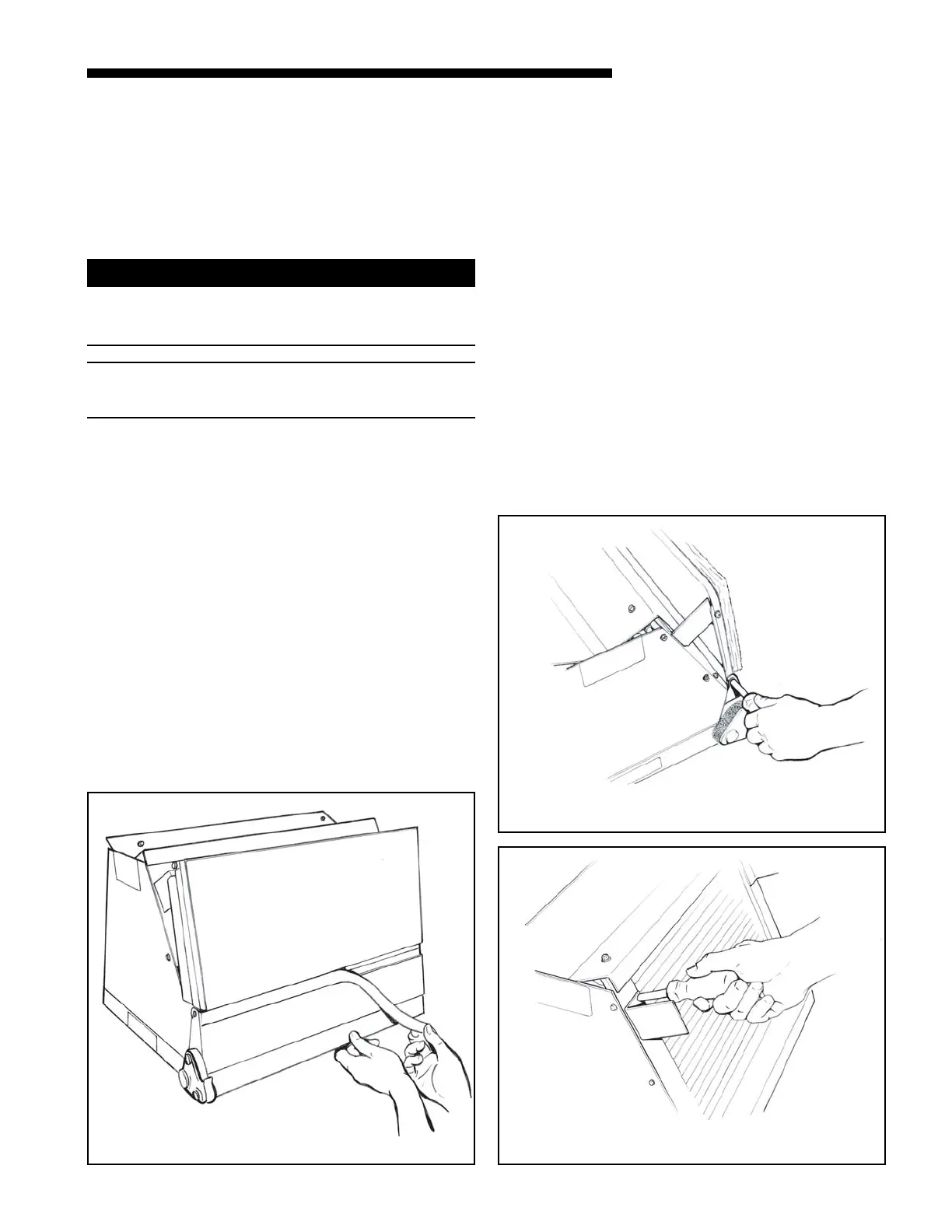
HORIZONTAL DRIP TRAY REMOVAL
7
DRIP TRAY BRACKET REMOVAL
8
DRIP PAN FOAM REMOVAL
6

 Loading...
