CVHE-SVN01C-EN
10
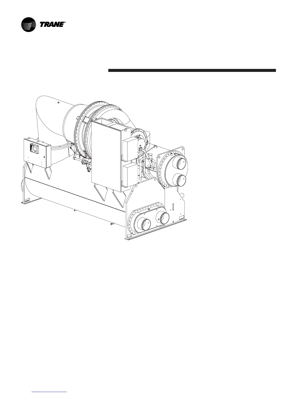
Figure 1. Typical chiller and its components
General Information
CVHF Shown from Right Front Angle View
Foundation Requirements
Provide rigid, non-warping
mounting pads or a concrete
foundation as a mounting surface for
the chiller. Ensure that the bade is of
sufficient strength and mass to
properly support the chiller at its full
operating weight (i.e., including
completed piping, and full operating
charges of refrigerant, oil and water.)
Table 2 and Table 3 give a summary
of standard tube bundle locations.
Table 4 indicates the weights of
various chiller options. Table 5
shows typical weights for Cooling
Only units.
Notice that the floor loading for all
sizes of CVHE, CVHF and CVHG
chillers is 50 pounds per square inch
[344 kPa].
To assure proper unit operation, the
chiller must be level within 1/16"
[1.6 mm] over its length and width
when set into place on the mounting
surface.
The Trane Company will not assume
responsibility for equipment
problems resulting from an
improperly designed or constructed
foundation.
 Loading...


