EasyManua.ls Logo

Trane CenTraVac User Manual

Trane CenTraVac
28 pages
To Next Page IconTo Next Page
To Previous Page IconTo Previous Page
Page #5 background imageLoading...
Page #5 background image
5
CVHE-SVN01C-EN
General Information
About this Manual
This manual describes proper
installation of Model CVHE, CVHF,
and CVHG 50 Hz and 60 Hz chillers
with the Tracer CH530 Controls
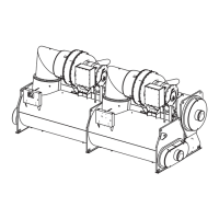
platform. See Figure 1 for an
illustration of a Centrifugal Chiller
with the Tracer CH530 Unit
Control Panel.
These chillers are equipped with
microcomputer-based control
systems whether standard cooling
or heat-recovery. A careful review of
this information along with the
submittal package provided for the
unit will assure that the chiller is
correctly installed.
Product Description Block
Trane 50 Hz and 60 Hz hermetic
CenTraVac units are defined by the
product definition and selection
system (PDS). Each unit is defined by
the product description block which
appears on the unit nameplate. A
service model number which
represents the unit as-built is
provided on the unit nameplate,
along with a specific unit service
number. Both these are utilized
whenever parts or service are
required. An example is provided in
the unit operation and maintenance
manual (CVHE-SVU01A-EN).
Commonly Used Acronyms
AFD = Adjustable Frequency Drive
ASME = American Society of
Mechanical Engineers
ASHRAE = American Society of
Heating, Refrigerating and Air
Conditioning Engineers
BAS = Building Automation System
LBU = La Crosse Business Unit
CABS = Auxiliary Condenser Tube-
Bundle Size
CDBS = Condenser Bundle Size
CESZ = Condenser Shell Size
CWR = Chilled Water Reset
DTFL = Delta-T at Full Load (i.e., the
difference between entering and
leaving chilled water temperatures at
design load)
EVBS = Evaporator Size
EVSZ = Evaporator Shell Size
FC = Free Cooling
GPM = Gallons-per-Minute
HGBP = Hot Gas Bypass
HVAC = Heating, Ventilating and Air
Conditioning
IE = Internally Enhanced Tubes
IPC = Interprocessor Communication
PFCC = Power Factor Correction
Capacitor
PSID = Pounds-per-Square-Inch
Differential
UCP = Chiller Control Panel
CH530 = Tracer CH530 Platform Unit
Control Panel
Unit Nameplate
The unit nameplate is located on the
left side of the unit control panel
(UCP). The following information is
provided on the unit nameplate.
1. Unit model and size descriptor
2. Unit serial number
3. Identifies unit electrical
requirements
4. Lists correct operating charge and
type of refrigerant
5. Lists unit test pressures and
maximum operating pressures
6. Identifies unit installation,
operation and maintenance
manuals
7. Product description block
Metric Conversion
For tables and charts in this manual,
the following conversions apply:
In. × 2.54 = cm
Ft. × 30.48 = cm
Lbs. × .453 = kg
Question and Answer IconNeed help?

Do you have a question about the Trane CenTraVac and is the answer not in the manual?

Trane CenTraVac Specifications

General IconGeneral
Compressor TypeCentrifugal
DimensionsVaries by model
Frequency50/60 Hz
RefrigerantR-123 or R-134a
Operating Range40°F to 65°F (Leaving Chilled Water Temperature)

Summary

Warnings and Cautions

General Information

About this Manual

Overview of the manual's scope and purpose for chiller installation.

Commonly Used Acronyms

Glossary of technical terms and abbreviations used in the document.

Product Description Block

Explanation of the unit's identifier and its components.

Unit Nameplate

Details found on the unit's identification plate.

Metric Conversion

Conversion factors for measurements used in the manual.

Responsibilities of Installing Contractor(s)

Key duties and tasks for contractors during unit installation.

ASHRAE Standard 15 Compliance

Guidelines for meeting safety standards for equipment rooms.

Unit Shipment

Information regarding the factory packaging and initial inspection of the chiller.

Storage

Precautions for storing the chiller before installation.

Recommended Unit Clearances

Required space around the chiller for service and maintenance.

Operating Environment

Conditions to consider for the chiller's installation location.

Storage Requirements if Chiller is not installed

Specific guidelines for storing the unit when not immediately installed.

Foundation Requirements

Criteria for preparing a stable and rigid mounting surface for the chiller.

Rigging

Recommended methods and safety precautions for lifting and moving the chiller.

Chiller Isolation

Methods to minimize vibration and sound transmission from the chiller.

Isolation Pads

Details on the placement and use of isolation pads under the chiller.

Spring Isolators

Instructions for installing and adjusting spring isolators for vibration control.

Unit Leveling

Procedures for ensuring the chiller is installed perfectly level.
Related product manuals