CVHE-SB-32A 54
IV. Motor Voltages for CTV Stepper Motor
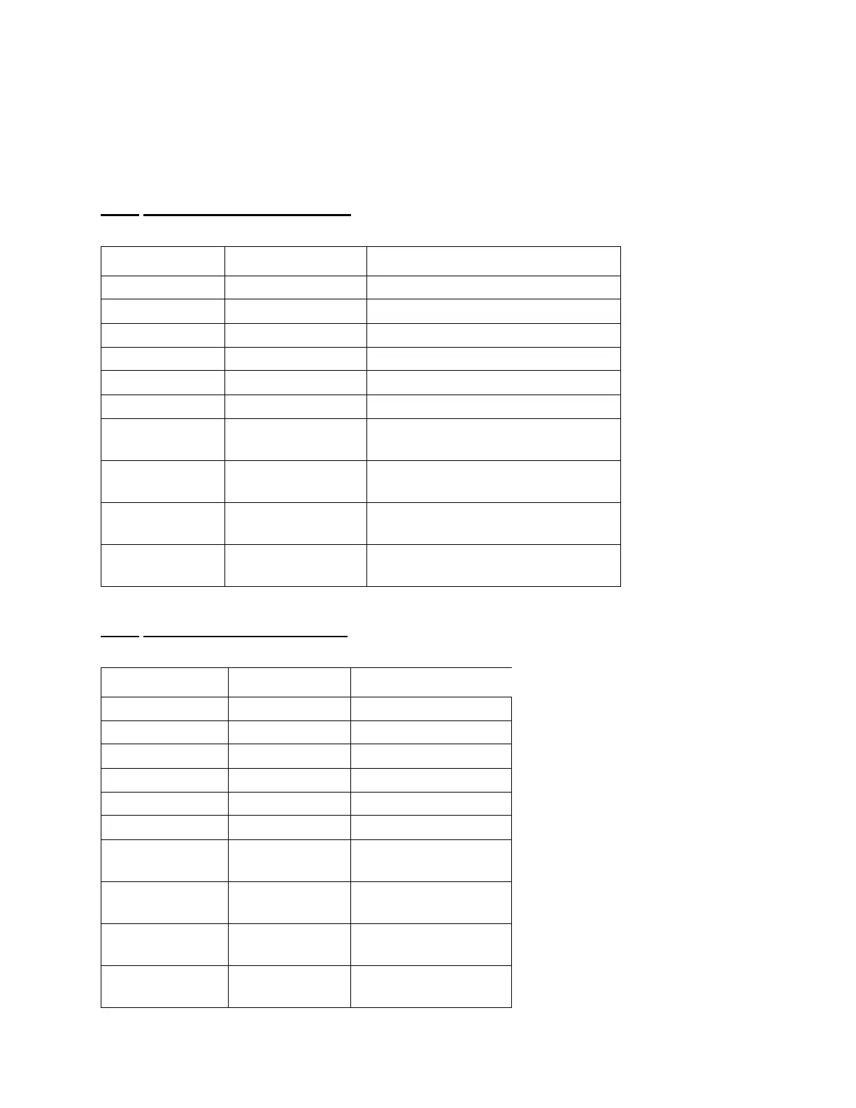
A. With the motor connector J6 (or J8) connected to the Stepper Board, and the Stepper
powered, measure the AC and DC voltages of the connector pins, and compare to Table 9 and
Table 10 .
Table 9
Motor Voltages with Actuator Holding
Table 10
Motor Voltages with Actuator Moving
Connector Pin AC Voltage DC Voltage
J6 - (4 to 3) 0 or (5.8 to 10) - 400 mV to +400 mV
J6 - (4 to 2) 5.8-8.2 + 400 mV, but not 0mV
J6 - (3 to 1) 0 or(5.8-10) - 400 mV to +400 mV
J6 - (3 to 2) 0 or(5.8-10) - 400 mV to +400 mV
J6-(3 to 1) 5.8 to 8.2 +400 mV, but not 0 mV
J6- (2 to1) 0 or (5.8-10) - 400 mV to +400 mV
J6 -(4 to
conduit)
0 or (5.8-8) (0.3-0.43) or (1.04- 1.135)
J6 -(3 to
conduit)
0 or (5.8-8) (0.3-0.43) or (1.04- 1.135)
J6 -(2 to
conduit)
0 or (5.8-8) (0.3-0.43) or (1.04- 1.135)
J6 -(1 to
conduit)
0 or(5.8 -8) (0.3-0.43) or (1.04- 1.135)
Connector Pin AC Voltage DC Voltage
J6 - (4 to 3) (16.6-25.9) -720 mV to +720 mV
J6 - (4 to 2) (20.8-27.5) -720 mV to +720mV
J6 - (4 to 1) 16.6-25.9) -720mVto +720mV
J6 - (3 to 2) 16.6-25.9) -720mV to +720mV
J6 - (3 to 1) 20.8-27.5) -720mV to+720mV
J6 - (2 to 1) (16.6 - 25.9) -720 mV to +720mV
J6 - (4 to
conduit)
(11.4 - 17.3) (9.1 -10.1)
J6 - (4 to
conduit)
(11.4 - 17.3) (9.1 -10.1)
J6 - (4 to
conduit)
(11.4 - 17.3) (9.1 -10.1)
J6 - (4 to
conduit)
(11.4 - 17.3) (9.1 -10.1)
 Loading...


