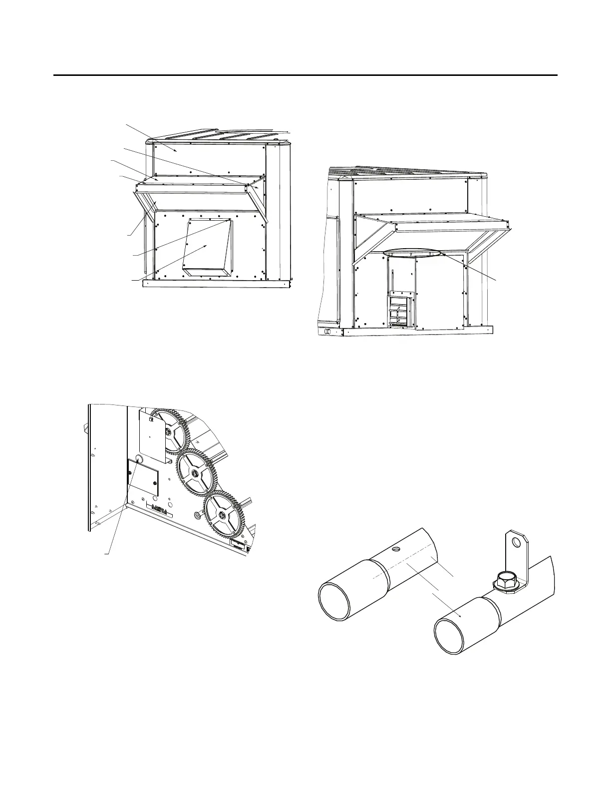
Figure 4. Barometric relief hood
Hood Triangle
Dimples for Powered
Exhaust Screws
Hood Top
Filler Panel
Mist Eliminator
FA Hood Front
Support
Barometric Relief
Hood
Installation - FIAECON102*
ACC-SVN264B-EN 7
Powered Exhaust
1. Remove aluminum barometric relief blade and discard.
2. Open 1-inch hole near the gear side of the economizer and
install
1-inch grommet.
Note: Gro
mmet in economizer parts bag.
Figure 5. Gear side of the economizer
1-inch Hole
for Wire Routing
3. Partially insert self-drilling screws in three dimples above
power exhaust opening and just below top economizer
hood. See Figure 6.
Note: Do not re-use baro
metric relief damper holes.
4. Install gasketing around perimeter of powered exhaust
assembly
.
5. Route the powered exhaust wire harness through the 1-
inch
hole near the gear side of the economizer.
6. Hang powered exhaust on three partially inserted screws
and
remove the slack in wire harness.
7. Attach powered exhaust with self-drilling screws. See
Figure 6.
8. Verify wire harness is clear of gears, doors, and any sharp
edges of metal.
9. Hook up electrical as described in literature
ACC-SVN57*-EN.
Figure 6. Powered exhaust
Dimples for
Powered Exhaust
Screws
Smoke Detector
1. If a smoke detector is installed, remove the copper or
aluminum pipe, and flexible tubing from above return air
opening, and all associated brackets.
Note: Grommets
are in the economizer parts bag.
2. Attach retaining bracket to pipe. See Figure 7 for the large
e
conomizer, drill a 1/8-inch hole drilled in pipe on opposite
side of existing breathing holes.
Notes:
• Re
taining bracket in the economizer parts bag.
• In Figure 7, intake holes must be down for unit to work.
Figure 7. Tubing
1/2-inch
3. Insert smoke detector pipe into hole of economizer (next to
RTEM board) and into back bracket inside economizer.
4. Using a self-drilling screw, attach retaining bracket to
e
conomizer. See Figure 8, p. 8.
5. Shorten flexible tubing and connect from the copper tubing
to the smo
ke detector unit.
 Loading...