RT-SVX072A-EN
113
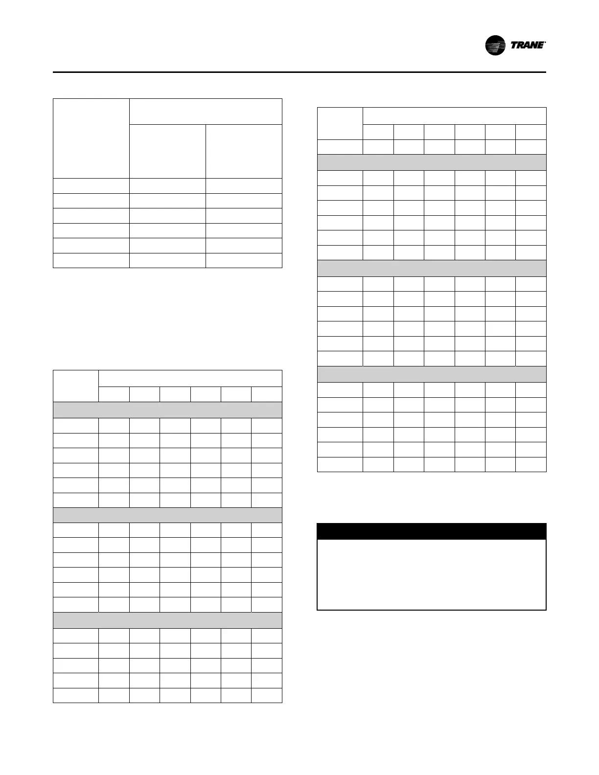
Table 48. O/A Damper travel adjustment
Position of
Connecting Rod
Damper Crank Arm Hole
Configuration
Standard and
Low Leak F/A
Dampers
(Figure 95, p.
112)
Ultra Low Leak
F/A Dampers
(Figure 96, p.
112)
Position #1 2–3 1–6
Position #2 2–4 2–6
Position #3 2–5 3–7
Position #4 2–6 4–8
Position #5 1–8 5–9
Position #6 1–7 5–7
Use Table 49, p. 113 to select the appropriate crank
arm hole configuration based on the following:
• specific unit
• operating CFM
• and return static pressure
Table 49. Outside air damper pressure drop (inches
w.c.) — air-cooled
CFM
Damper Position
#1 #2 #3 #4 #5 #6
20, 25 Ton
4000 0.03 0.04 0.06 0.13 0.16 0.33
6000 0.03 0.04 0.10 0.20 0.30 0.90
8000 0.19 0.21 0.32 0.52 0.75 1.75
9000 0.30 0.35 0.48 0.76 1.08 2.40
10000 0.45 0.51 0.70 1.05 1.57 -
11000 0.62 0.71 0.95 1.42 2.15 -
30
6000 0.03 0.04 0.07 0.15 0.20 0.43
8000 0.03 0.05 0.11 0.21 0.30 0.90
10000 0.15 0.19 0.26 0.43 0.62 1.50
11000 0.20 0.25 0.37 0.60 0.85 1.85
12000 0.31 0.36 0.50 0.79 1.10 2.40
13000 0.42 0.48 0.62 0.97 1.42 -
40, 48 Ton
8000 0.03 0.04 0.08 0.16 0.21 0.52
10000 0.03 0.05 0.11 0.21 0.30 0.90
12000 0.10 0.13 0.21 0.38 0.55 1.40
14000 0.20 0.25 0.37 0.60 0.85 1.85
16000 0.41 0.46 0.60 0.94 1.38 -
Table 49. Outside air damper pressure drop (inches
w.c.) — air-cooled (continued)
CFM
Damper Position
#1 #2 #3 #4 #5 #6
18000 0.56 0.65 0.74 1.28 1.92 -
50, 55 Ton
10000 0.03 0.04 0.09 0.18 0.23 0.55
14000 0.09 0.12 0.20 0.35 0.50 1.36
18000 0.31 0.36 0.50 0.79 1.10 -
20000 0.45 0.51 0.70 1.05 1.57 -
22000 0.58 0.66 0.75 1.30 1.95 -
24000 0.75 0.88 1.10 1.75 2.50 -
(60, 70, 75 Ton) Units
14000 0.03 0.04 0.12 0.25 0.35 1.05
18000 0.19 0.21 0.32 0.52 0.75 1.75
22000 0.45 0.51 0.70 1.05 1.57 -
26000 0.70 0.80 1.02 1.58 2.30 -
28000 0.88 1.03 1.30 2.20 - -
30000 1.05 1.22 1.55 2.65 - -
(90 to 130 Ton) Units
27000 0.31 0.36 0.50 0.79 1.10 2.40
32000 0.55 0.64 0.72 1.25 1.88 -
36000 0.75 0.88 1.10 1.75 2.50 -
40000 1.00 1.18 1.50 2.50 - -
43000 1.20 1.42 1.92 - - -
46000 1.40 1.58 2.29 - - -
Compressor Startup (All
Systems)
NNOOTTIICCEE
CCoommpprreessssoorr FFaaiilluurree!!
FFaaiilluurree ttoo ffoollllooww iinnssttrruuccttiioonn bbeellooww ccoouulldd rreessuulltt iinn
ccoommpprreessssoorr ffaaiilluurree..
UUnniitt mmuusstt bbee ppoowweerreedd aanndd ccrraannkkccaassee hheeaatteerrss
eenneerrggiizzeedd aatt lleeaasstt 88 hhoouurrss BBEEFFOORREE ccoommpprreessssoorrss
aarree ssttaarrtteedd..
1. Ensure that the “System” selection switch at the
remote panel is in the “Off” position.
2. Before closing the disconnect switch, ensure that
the compressor discharge service valve for each
circuit is back seated.
UUnniitt SSttaarrttuupp

 Loading...


