10
RT-SVX24Q-EN
General Information
Unit Nameplate
One Mylar unit nameplate is located on the outside
upper left corner of the control panel door. It includes
the unit model number, serial number, electrical
characteristics, weight, refrigerant charge, unit wiring
diagram numbers, as well as other pertinent unit data.
A small metal nameplate with the Model Number,
Serial Number, and Unit Weight is located just above
the Mylar nameplate, and a third nameplate is located
on the inside of the control panel door.
Compressor Nameplate
The Nameplate for the Scroll Compressor is located on
the compressor lower housing. Max amps is listed on
the nameplate and is the absolute highest amp load on
the compressor at any operating condition (does not
include locked rotor amps or inrush). This value should
never be exceeded.
Unit Description
Table 1. Available tonnages
Air-Cooled Tonnages
Evaporative Condenser
Tonnages
90 100
105 118
120 128
130 140
150 162
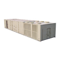
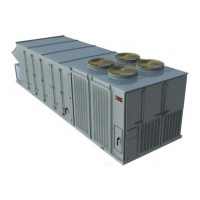
Each single-zone rooftop air conditioner ships fully
assembled from the factory. An optional roof curb,
specifically designed for the S_HJ units is available
from Trane. The roof curb kit must be field assembled
and installed according to the latest edition of the roof
curb installation manual.
Trane Commercial Rooftop Units are controlled by a
microelectronic control system that consists of a
network of modules and are referred to as Unit Control
Modules (UCM). The acronym (UCM) is used
extensively throughout this document when referring
to the control system network. These modules through
Proportional/Integral control algorithms perform
specific unit functions which provide the best possible
comfort level for the customer.
They are mounted in the control panel and are factory
wired to their respective internal components. They
receive and interpret information from other unit
modules, sensors, remote panels, and customer binary
contacts to satisfy the applicable request for
economizing, mechanical cooling, heating, and
ventilation. Refer to the following discussion for an
explanation of each module function.
Table 2. Resistance input vs. setpoint temperature
RTM cooling or
heating
setpoint input
used as the
source for a
ZONE temp
setpoint (°F)
RTM cooling
setpoint input
used as the
source for
SUPPLY AIR
temp setpoint
cooling (°F)
Resistance
(Ohms) Max.
Tolerance 5%
40 40 1084
45 45 992
50 50 899
55 55 796
60 60 695
65 65 597
70 70 500
75 75 403
80 80 305
n/a
85 208
n/a
90 111
Table 3. RTM resistance value vs. system operating
mode
Resistance applied
to RTM MODE input
Terminals (Ohms)
Max. Tolerance 5%
Constant Volume Units
Fan Mode
System Mode
2320 Auto Off
4870 Auto Cool
7680 Auto Auto
10770 On Off
13320 On Cool
16130 On Auto
19480 Auto Heat
27930 On Heat
Rooftop Module
(RTM - Standard on all units)
The rooftop Module (RTM) responds to cooling,
heating, and ventilation requests by energizing the
proper unit components based on information received
from other unit modules, sensors, remote panels, and
customer supplied binary inputs. It initiates supply fan,
exhaust fan, exhaust damper, positioning or variable
frequency drive output, and economizer operation
based on that information.

 Loading...


