62
RT-SVX24Q-EN
removed. To locate and remove these channels, refer
to Figure 45, p. 62 and use the following procedures.
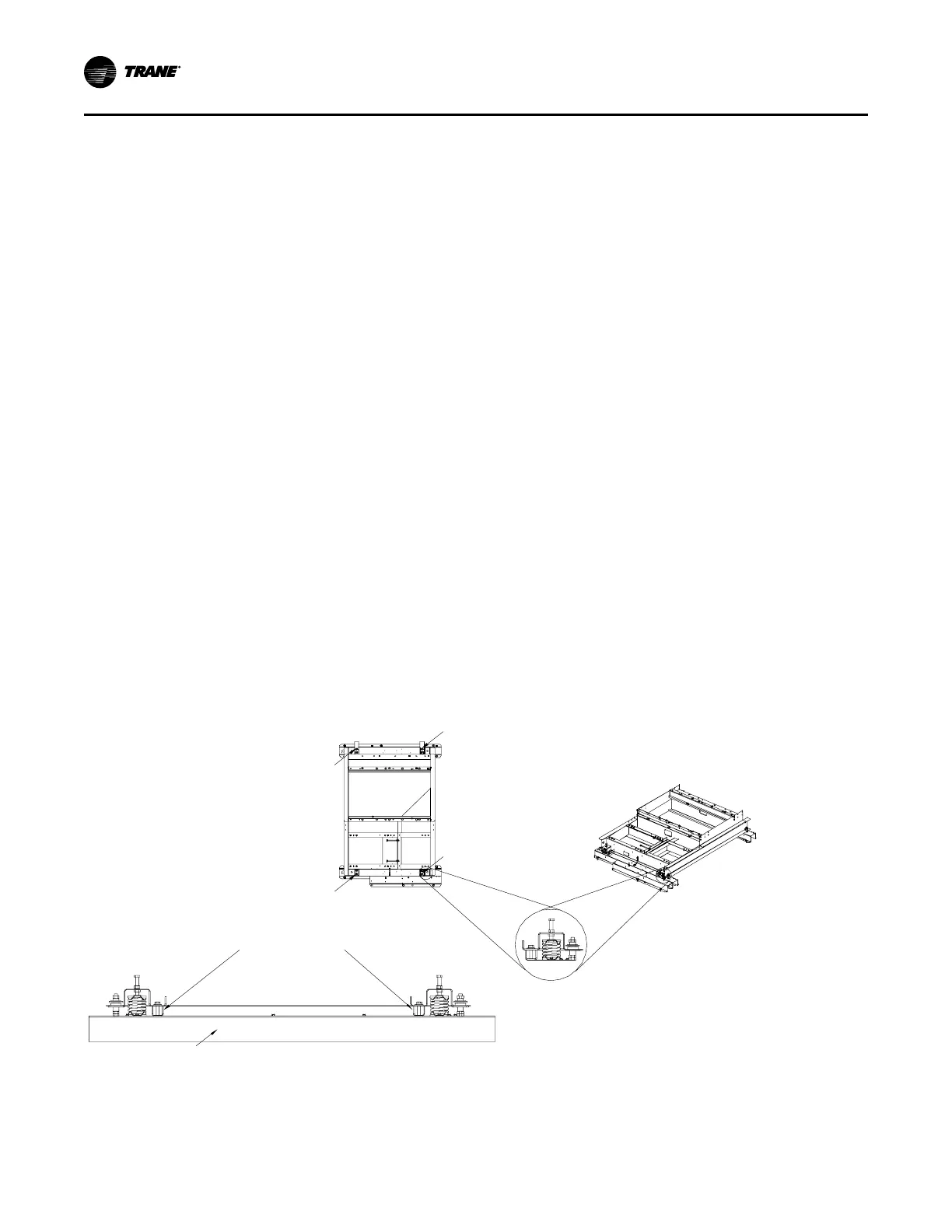
Spring Isolators
Spring isolators for the supply and/or exhaust fan are
shipped with the isolator adjusting bolt backed out.
Field adjustment is required for proper operation.
Figure 45, p. 62 shows isolator locations. To adjust the
spring isolators use the following procedure.
1. Remove and discard the shipping tie down bolts
but leave the shipping channels in place during the
adjustment procedure. See Figure 45, p. 62.
2. Tighten the leveling bolt on each isolator until the
fan assembly is approximately 1/4" above each
shipping channel.
3. Secure the lock nut on each isolator.
4. Remove the shipping channels and discard.
Remove Evaporative Condenser Fan
Shipping Brackets
IImmppoorrttaanntt:: Remove fan shipping brackets before start-
up. Failure to remove brackets could result
in fan damage.
Evaporative condensers are shipped with fan shipping
brackets to reduce damage caused by vibration during
shipment. The fan shipping brackets must be removed
prior to unit start-up. To remove the shipping brackets
start from the side opposite to the drain actuator (see
Figure 135, p. 177):
1. Loosen the screw for the bracket that holds the
inlet louvers below the door side.
2. Remove inlet louvers and set to the side.
NNoottee:: Service technician may need to step on the
horizontal surface of FRP coated base.
Step with care.
3. Unscrew the bolt in the middle of the door. Keep
the bolt in a safe place.
4. Lift one door with handle until it touches the top.
Swivel bottom of door to remove it from the door
opening and set it to the side.
5. Slide and remove the middle mist eliminator
section so that the shipping bracket is visible.
6. Use screw gun to unscrew the two screws that hold
the fan shipping bracket. The bracket should drop
down but still remain engaged with a hook on the
bracket.
7. Go to the other side of the unit and follow the
procedure for inlet louver and door removal (see
steps 1 - 6).
8. Hold the bracket with one hand and remove
remaining two screws.
9. Remove the bracket and all the removed screws
from the unit.
IImmppoorrttaanntt:: Make sure there are no screws
remaining in the coil area.
10. Reinstall inlet louvers, mist eliminators and louvers.
11. Check that the direction of arrow on the inlet louver
is correct.
Figure 45. Removing fan assembly shipping hardware
Loc3
L
oc4
Loc1
Loc2
Shipping
Channels
Fan Assembly Rail
Detail “A”
4 Locations
Top View
Front View
IInnssttaallllaattiioonn

 Loading...


