182
RT-SVX24Q-EN
Figure 138. Flue gas carbon dioxide and oxygen
measurements - same as Figure 51, p.73 in current
catalog.
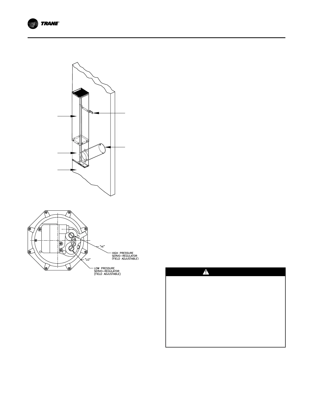
Flue
Extension
Mounting
Bracket
Flue Tube
Vent Cap
Assembly
Heat Section
Vertical Support
Figure 139. High/low pressure regulator
Full Modulating Gas Furnace
Full Modulating gas heaters are available for the 850,
1100, 1800, 2500 MBH heater sizes:
• The firing rate of the 850 MBH modulating heater
can vary from 10% to 100% of the 850 MBH.
• The firing rate of the 1100, 1800 and 2500 MBH can
vary from 5% to 100% of it's nameplate value.
Heat Exchanger
The heat exchanger drum, tubes and front and rear
headers are constructed from stainless steel alloys.
Unit Control
The unit is controlled by a supply air temperature
sensor located in the supply air stream for VAV units.
CV units have two sensors, one located in the supply
air stream and the zone sensor. The temperature
sensor signal is sent to the Heat module of the
IntelliPak Unit Control. The control signal from the Heat
Module signal is directly proportional to 0-10 VDC. The
higher the voltage signal, the lower the call for heat.
The 0-10 VDC signal controls the air damper actuator
which is mounted on the end of the air damper shaft.
As the actuator rotates clockwise, more combustion air
passes through the combustion air blower. In turn, the
gas butterfly valve opens more through a directly
connected linkage, resulting in a higher rate of firing.
1. Use tables in “Voltage Imbalance,” p. 105 to
program the following system components for
operation by scrolling through the Human Interface
displays :
GGaass HHeeaatt
• Supply Fan (On)
• Variable Frequency Drive (100% Output, if
applicable)
• RTM Occ/Unocc Output (Unoccupied)
• High Fire (90%)
Turn the 115 volt control circuit switch located in
the heater control panel to the “On” position.
Open the manual gas valve, located in the gas heat
section.
2. Once the configuration for the appropriate heating
system is complete, press the NEXT key until the
LCD displays the “Start test in __Sec.” screen. Press
the + key to designate the delay before the test is to
start. This service test will begin after the TEST
START key is pressed and the delay designated in
this step has elapsed. Press the ENTER key to
confirm this choice.
3. Press the TEST START key to start the test.
Remember that the delay designated in step 2 must
elapse before the system will begin to operate.
WWAARRNNIINNGG
RRoottaattiinngg CCoommppoonneennttss!!
FFaaiilluurree ttoo ddiissccoonnnneecctt ppoowweerr bbeeffoorree sseerrvviicciinngg ccoouulldd
rreessuulltt iinn rroottaattiinngg ccoommppoonneennttss ccuuttttiinngg aanndd ssllaasshhiinngg
tteecchhnniicciiaann wwhhiicchh ccoouulldd rreessuulltt iinn ddeeaatthh oorr sseerriioouuss
iinnjjuurryy..
DDuurriinngg iinnssttaallllaattiioonn,, tteessttiinngg,, sseerrvviicciinngg aanndd
ttrroouubblleesshhoooottiinngg ooff tthhiiss pprroodduucctt iitt mmaayy bbee
nneecceessssaarryy ttoo wwoorrkk wwiitthh lliivvee aanndd eexxppoosseedd rroottaattiinngg
ccoommppoonneennttss.. HHaavvee aa qquuaalliiffiieedd oorr lliicceennsseedd sseerrvviiccee
iinnddiivviidduuaall wwhhoo hhaass bbeeeenn pprrooppeerrllyy ttrraaiinneedd iinn
hhaannddlliinngg eexxppoosseedd rroottaattiinngg ccoommppoonneennttss,, ppeerrffoorrmm
tthheessee ttaasskkss..
4. Once the system has started, check the appearance
of the flame through the sight glass provided on the
front of the heat exchanger. In appearance, a
normal flame has a clearly defined shape, and is
UUnniitt SSttaarrttuupp

 Loading...


