RTAA-SVX01A-EN 51
Installation — Electrical
Installer-Supplied Components
All wiring must comply with local codes and the National Electrical Code. The
installing (or electrical) contractor must provide and install the system inter-
connecting wiring, as well as the power supply wiring. It must be properly
sized and equipped with the appropriate fused-disconnect switches. The type
and installation location(s) of the fused-disconnects must comply with all
applicable codes.
The installer must provide the following components if not ordered with the
unit:
• Power supply wiring (in conduit) for all field-wired connections.
• All control (interconnecting) wiring (in conduit) for field supplied devices.
• Fused-disconnect switches.
Remote Evaporator Only:
• Control wiring between the outdoor unit and the evaporator terminal box.
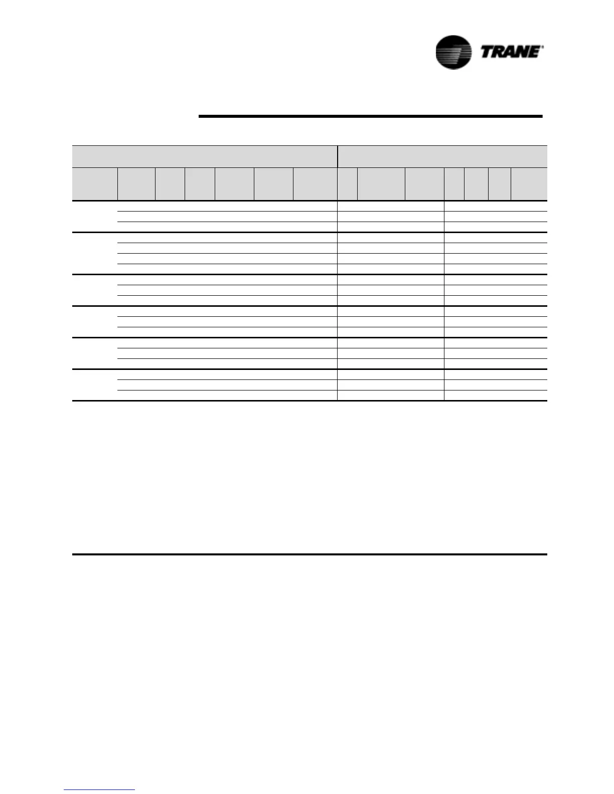
Table 11 Electrical Data - Pump Package Option
Unit Wiring
Motor Data
Unit Size
Rotated
Voltage
Pump
HP
Pump
FLA MCA (2) MOP (1)
Rec Time
Delay or
RDE (3) Qty
Comp(Ea)
RLA (4) LRA (7) Qty
Fans
(Ea)
KW FLA
Control
KW (6)
RTAA 70
460/60 2 3.1 136 175 150 2 50/50 330/330 8 1.0 2.5 0.75
460/60 3 4.1 137 175 150 2 50/50 330/330 8 1.0 2.5 0.75
460/60 5 6.6 139 175 175 2 50/50 330/330 8 1.0 2.5 0.75
RTAA 80 460/60 2 3.1 163 200 200 2 62/62 380/380 8 1.0 2.5 0.75
460/60 3 4.1 164 225 200 2 62/62 380/380 8 1.0 2.5 0.75
460/60 5 6.6 166 225 200 2 62/62 380/380 8 1.0 2.5 0.75
460/60 7.5 10.3 170 225 200 2 62/62 380/380 8 1.0 2.5 0.75
RTAA 90
460/60 3 4.1 194 250 225 2 84/62 410/380 9 1.0 2.5 0.75
460/60 5 6.6 196 250 225 2 84/62 410/380 9 1.0 2.5 0.75
460/60 7.5 10.3 200 250 225 2 84/62 410/380 9 1.0 2.5 0.75
RTAA 100
460/60 3 4.1 218 300 250 2 84/84 410/410 10 1.0 2.5 0.75
460/60 5 6.6 221 300 250 2 84/84 410/410 10 1.0 2.5 0.75
460/60 7.5 10.3 224 300 350 2 84/84 410/410 10 1.0 2.5 0.75
RTAA 110
460/60 3 4.1 239 300 300 2 101/84 522/410 10 1.0 2.5 0.75
460/60 5 6.6 242 300 300 2 101/84 522/410 10 1.0 2.5 0.75
460/60 7.5 10.3 246 300 300 2 101/84 522/410 10 1.0 2.5 0.75
RTAA 125
460/60 3 4.1 256 350 300 2 101/101 522/522 10 1.0 2.5 0.75
460/60 5 6.6 259 350 300 2 101/101 522/522 10 1.0 2.5 0.75
460/60 7.5 10.3 263 350 300 2 101/101 522/522 10 1.0 2.5 0.75
(1) MOP - Maximum Overcurrent Protection - may be either type breaker (UL/CSA) or with circuit breakers (CSA only). MOP = 225 percent of the largest
compressor RLA plus 100 percent of the second compressor plus the sum of the condenser fans FLAs per NEC 440-22.
(2) MCA - Minimum Circuit Ampacity - 125 percent of largest compressor RLA plus 100 percent of second compressor plus the sum of the condenser
fans FLAs per NEC 440-33.
(3) RECOMMENDED TIME DELAY OR DUAL ELEMENT (RDE) FUSE SIZE: 150 percent of the largest compressor RLA plus 100 percent of the
second compressor RLA and the sum the condenser fan FLAs.
(4) RLA -Rated Load Amps -rated in accordance with UL Standard 465.
(5) Local codes may take precedence.
(6) Control kw includes operational controls only. Does not include heat tapes.
(7) LRA - Locked Rotor Amps -based on full winding start units.
(8) VOLTAGE UTILIZATION RANGE:
Rated Voltage Utilization Range
200/60 180-220
230/60 208-254
460/60 414-506
575/60 516-633
400/50 340-460
(9) 60 HZ UNITS - A 115/60/1, 15 amp. customer provided power connection is required to power the evaporator heat tape 420 watts
(10) 50 HZ UNITS - A separate 220/50/1 15 amp. customer provided power connection is needed to power evaporator heat tape 420 watts @ 220 volts.
 Loading...


