58 RTAA-SVX01A-EN
Installation — Electrical
2. Isolated 2-10 VDC Voltage Source Input.
Set DIP Switch SW1-1 of Options Module 1U2 to “OFF”. Connect the voltage
source to terminals TB1-4 (+) and TB1-5 (-) on Options Module IU2. CWS is
now based on the following equation:
CW Setpoint °F = (VDC x 125) - 16.25
Sample values for CWS vs. VDC signals are shown in Table 14 .
3. Isolated 4-20 mA Current Source Input.
Set DIP Switch SW1-1 of Options Module 1U2 to “ON”. Connect the current
source to terminals TB1-4 (+) and TB1-5 (-). CWS is now based on the
following equation:
Setpoint °F = (mA x 4.0625) - 16.25
Sample values for CWS vs., mA signals are shown in Ta ble 14.
NOTE: The negative terminal TB1 -5 is referenced to the UCM chassis
ground. To assure correct operation, 2-10 VDC or 4-20 mA signals must be
isolated or “floating” with respect to the UCM chassis ground.
Minimum setpoint =
0 F(2.0
VDC input)
Maximum setpoint =
65 F (
9.4 VDC input)
Maximum continuous input voltage = 15 VDC
Input impedance (SW1-1 on) = 40.1 Kohms
Minimum setpoint = 0F(40mA)
Maximum setpoint = 65 F (18.8 mA)
Maximum continuous input voltage = 30 mA
Input impedance (SW1-1 off) = 499 ohms
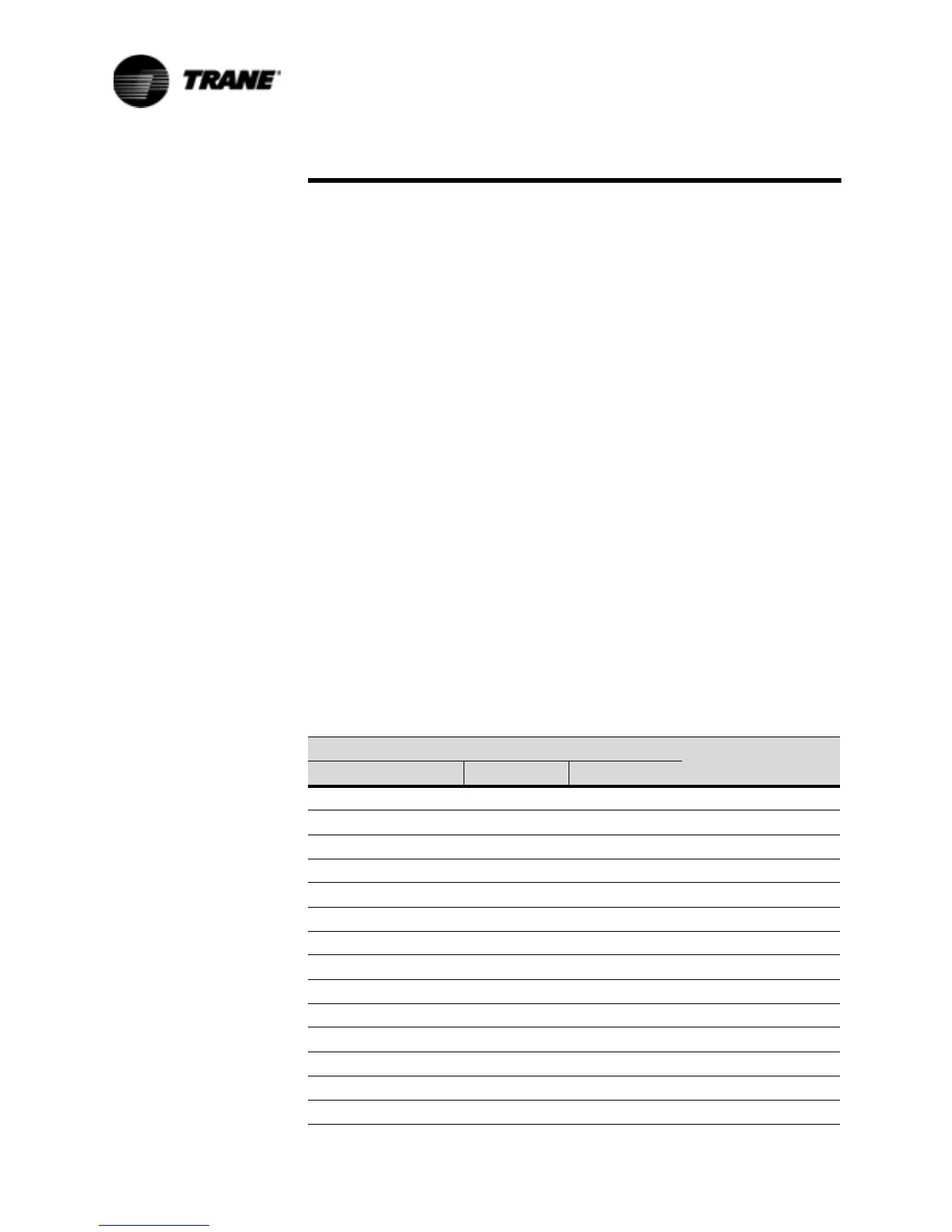
Table 14 Input Values Vs. External Chilled Water Setpoint
Inputs
Resulting Chilled
Water Setpoint (F)
Resistance (Ohms) Current (ma) Voltage (Vdc)
944330 4.0 2.0 0.0
686092 5.2 2.6 5.0
52946 6.5 3.2 10.0
42434 7.7 3.9 15.0
34889 8.9 4.5 20.0
29212 10.2 5.1 25.0
24785 11.4 5.7 30.0
21236 12.6 6.3 35.0
18327 13.8 6.9 40.0
15900 15.1 7.6 45.0
13844 16.3 8.2 50.0
12080 17.5 8.8 55.0
10549 18.8 9.4 60.0
9050 20.0 10.0 65.0
 Loading...


