8 RTAA-SVX01A-EN
General Information
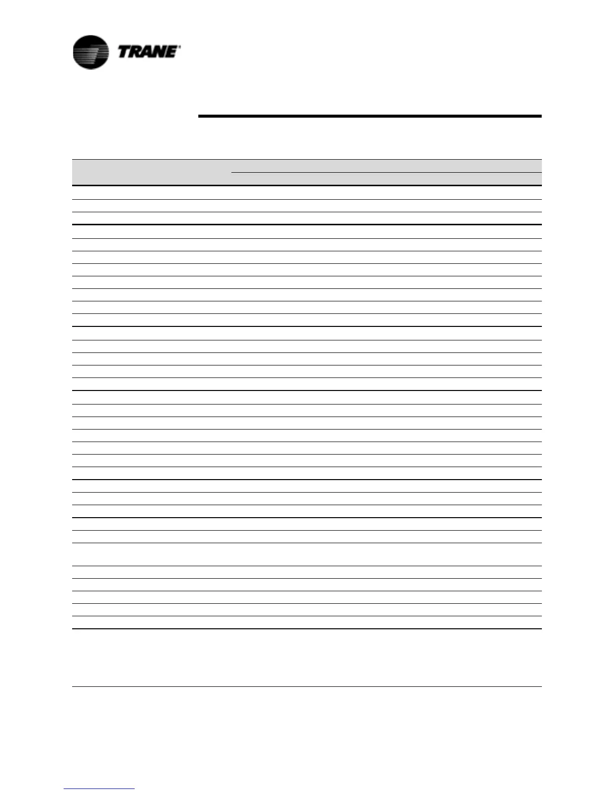
Table 1 General RTAA Mechanical Specifications
Size
70 80 90 100 110 125
Compressor
Quantity 222222
Nominal Size (Tons)(1) 35/35 40/40 50/40 50/50 60/50 60/60
Evaporator
Water Storage (Gallons) 39.8 37.8 34.4 32.1 53.4 45.8
(Liters) 150.6 143.1 130.2 121.5 202.1 173.4
Min. Flow (GPM) 84 96 108 120 132 150
(L/Sec) 5.3 6.1 6.8 7.6 8.3 9.5
Max. Flow (GPM) 252 288 324 360 396 450
(L/Sec) 15.9 18.2 20.4 22.7 25.0 28.4
Refer to Pump Package Section for water storage of Pump and accocated piping.
Condenser
Qty of Coils 444444
Coil Length (Ft)(1) 13/13 13/13 14/13 14/14 17/14 17/17
Coil Height (In) 42 42 42 42 42 42
Number of Rows 222222
Condenser Fans
Quantity (1) 4/4 4/4 5/4 5/5 5/5 5/5
Diameter (In) 303030303030
Total Airflow (CFM) 68,380 68,380 73,365 78,355 82,950 87,550
Nominal RPM 855 855 855 855 855 855
Tip Speed (Ft./Min.) 6715 6715 6715 6715 6715 6715
Motor HP (Ea.) 1.1 1.1 1.1 1.1 1.1 1.1
Min. Starting/Oper. Ambient
Std Unit (Deg. F) 15 15 15 15 15 15
Low Amb. (Deg. F) -10 -10 -10 -10 -10 -10
General Unit
Refrigerant HCFC-22 HCFC-22 HCFC-22 HCFC-22 HCFC-22 HCFC-22
No. of Independent
Refrigerant Circuits 222222
% Min. Load (3) 101010101010
Refrig Charge (Lb) (1) 58/58 61/61 73/61 73/73 98/73 98/98
(Kg) 26/26 27/27 33/27 33/33 44/33 44/44
Oil Charge (Qts) (1.4) 10/10 10/10 12/10 12/12 12/12 12/12
(L) 10.6/10.6 10.6/10.6 12.7/10.6 12.7/12.7 12.7/12.7 12.7/12.7
Notes:
1. Data containing information on two circuits shown as follows: ckt1/ckt2
2. Minimum start-up/operating ambient based on a 5 mph wind across the condenser.
3. Percent minimum load is for total machine, not each individual circuit.
4. Trane Part Change # Oil-31 (see service bulletin SCOM-SB-1)
 Loading...


