RTAA-SVX01A-EN 121
Maintenance
4. After the level has been determined, remove the sight glass and hoses.
Oil Filter Change
NOTE: Routine changing of the oil or the oil filter is not recommended. The
oil filter is oversized for this application and should not require replacement.
The oil and filter should be replaced only if analysis reveals that the oil is
contaminated. Oil type and system capacities are shown in Table 1.
Pressure drops across the oil filter are shown in Figure 41. Oil filter pressure
drop is the difference between the pressure at the oil filter cover plate
Schrader valve and the pressure at the compressor oil supply Schrader valve,
on top of the compressor.
To change the oil filter in the unit, refer to Figure 40 and follow the steps listed
below.
1. Shut off the compressor and disconnect all electrical service to the com-
pressor.
2. Connect manifold gauge sets to the backseat ports of the suction and dis-
charge service valves and the Schrader valve on the oil filter cover plate.
3. Frontseat the suction and discharge service valves. Separate the Aero-
quip valve coupling, or close valve at the oil supply to the compressor or,
on later chillers, frontseat the oil supply line angle valve.
4. Recover refrigerant from the three connections in Step 2.
NOTE: The Schrader valve may have a high quantity of oil.
WARNING
Components Under High Pressure!
Failure to relieve pressure before removing filter retaining bolt
could result in death or serious injury
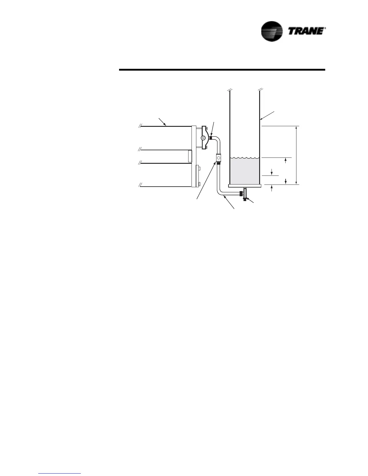
Figure 39 System Oil Level Specifications
&RPSUHVVRU
%DFNVHDW
3RUWRQ
'LVFKDUJH
5HIULJHUDQW/LTXLG
/LQH6LJKWJODVV
SXUFKDVHGORFDOO\
´5HIULJHUDWLRQ+RVH
9DOYH
0LQLPXP2LO/HYHO
³
´
1RPLQDO
2LO
/HYHO
´0D[LPXP
2LO/HYHO
2LO6HSDUDWRU
 Loading...

