RTAA-SVX01A-EN 63
Installation — Electrical
The microprocessing board can now be replaced in the display box with its
four attaching screws.
Remote CLD Panel Wiring
The Remote CLD requires a 24 VAC power source and a shielded, twisted-
pair wire between the panel and the Clear Language Display. See Figure 30.
As shown in Figure 31, the wire runs from terminals J3A-1(+) and J3A-2(-) in
the unit's buffer module (1U7) to terminals J1(+) and J1(-) in the Remote CLD.
Be sure that one lead is connected to the (+) terminal at each end and the
other lead is connected to the (-) terminal at each end.
For units #2, #3 and #4 wire similarly as shown in Figure 31.
Do not run the shielded, twisted-pair wire in a conduit that also contains
circuits of greater than 30 volts. Attach the shield to a grounding lug in the
unit's control panel. Cut and tape the shield at the Remote CLD panel, as
shown in Figure 30.
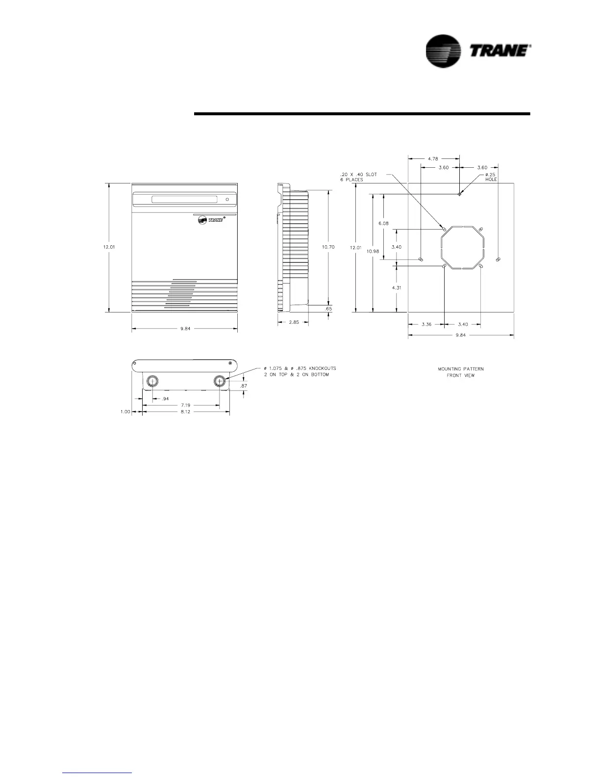
Figure 29 Remote CLD Panel Mounting Holes and Electrical Access Knockouts
 Loading...

