64 RTAA-SVX01A-EN
Installation — Electrical
Connect the 24 VAC power supply to terminals J2A and J2B in the Remote
CLD panel. The polarity of the power source is not a concern, but the power
source must be grounded to terminal J2Gnd.
NOTE: A field-supplied Class 2, 24 VAC, 40 VA transformer can be used as a
power supply for the Remote CLD panel.
NOTE: Both a Remote CLD and a Tracer unit can be connected to the UCM.
ICS Address Setting
The setting of the ICS address for the Remote CLD is not necessary.
Multiple Unit Operation
In a multiple unit configuration, the Remote CLD Panel has the capability to
communicate with up to four units. Each unit requires a separate communi-
cation link with the Remote CLD panel.
Terminal strip TB4 is used to wire in the second, third and fourth units to the
Remote CLD. TB4 is labeled as shown below:
Terminals 1-3 are for the second unit.
Terminals 4-6 are for the third unit.
Terminals 7-9 are for the fourth unit.
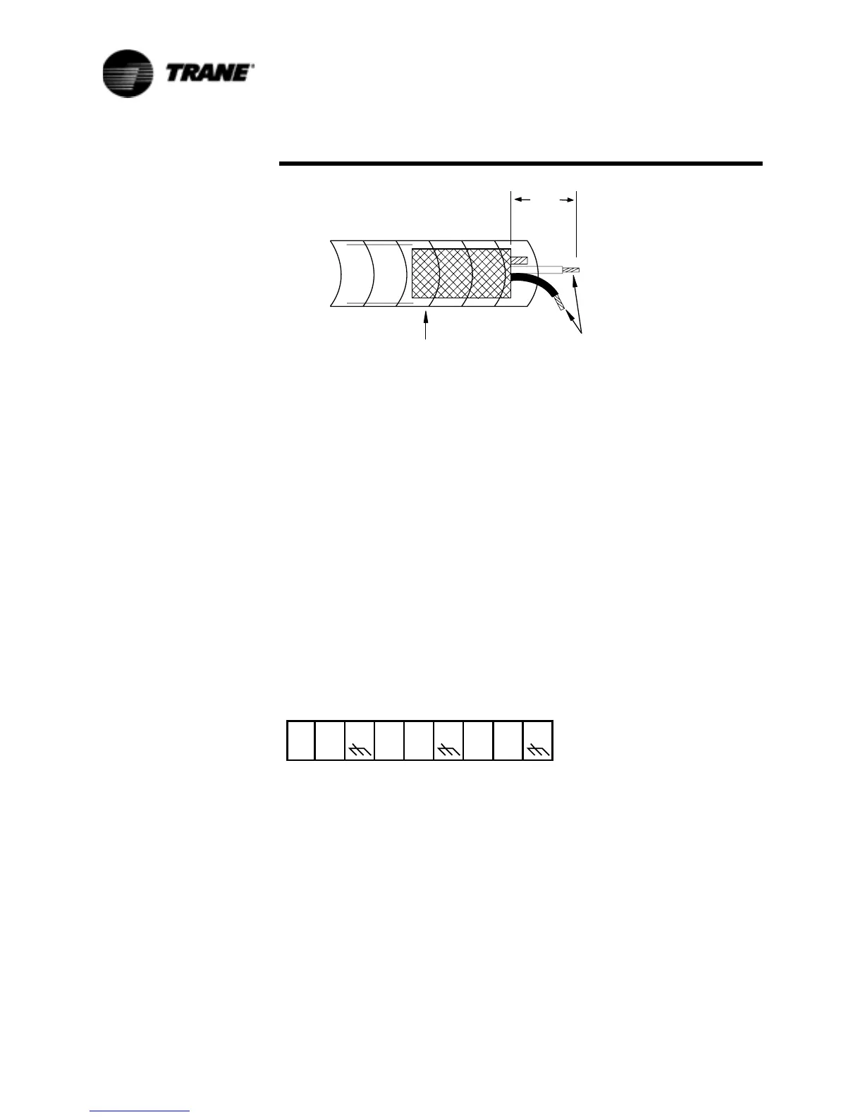
Figure 30 Shielded, Twisted Pair Communication LInk at the
Remote CLD Panel
7RAPTAPEAROUND
EXPOSEDFOILSHIELD
ANDBARESHIELDWIRE
#ONNECTLEADSTO
2EMOTE#,$0ANEL
-AX
#UTBACKBARE
SHIELDWIRE
 Loading...

