RLC-SVX19A-E4
17
Installation Requirements
Clearances
When installing the unit, provide enough space around
the unit to allow the installation and maintenance
personnel unrestricted access to all service points.
Unobstructed fl ow of condenser air is essential to
maintain chiller capacity and operating effi ciency. When
determining unit placement, give careful consideration to
ensuring a suffi cient air fl ow across the condenser coils
heat-transfer surface.
In case of enclosure around the unit, the height of the
enclosure must not be higher than the unit itself. If the
enclosure is higher than the unit, restrictive airfl ow
louvers should be fi tted to ensure fresh air supply.
Unit Isolation and Leveling
Provide a foundation with suffi cient strength and mass
to support the unit operating weight (that is, including
completed piping, full operating charges of refrigerant
and oil, and water). Refer to unit operating weights.
The unit must be leveled within 6mm over its length
and width. Use shims as necessary to level the unit. For
additional reduction of sound and vibration, install the
optional elastomeric isolators.
Isolator and Sound Emissions
The most effective form of isolation is to locate the
unit away from any sound sensitive area. Structurally
transmitted sound can be reduced by elastomeric
vibration eliminators. Spring isolators are not
recommended. Consult an acoustical engineer in critical
sound applications.
For maximum isolation effect, isolate water lines and
electrical conduit. Rubber isolated piping hangers can
be used to reduce the sound transmitted through water
piping. To reduce sound transmitted through electrical
conduit, use fl exible electrical conduit.
EU and Local Regulations codes on sound emissions
should always be considered. Since the environment
in which a sound source is located affects the sound
pressure, unit placement must be carefully evaluated.
Sound power levels for Sintesis RTAF are available on
request.
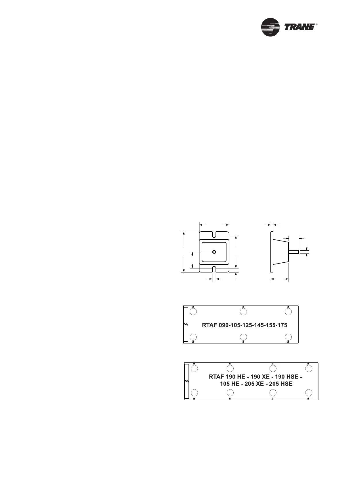
Neoprene Isolators Installation (Optional)
Isolators are ready to install. Mountings have to
be placed on a rigid and level foundation. External
equipment should not transmit additional vibration
to the chiller. The position of elastomeric isolator and
weight per point are given in the submittal which is
supplied with the chiller.
1. Secure the isolators to the mounting surface using
the mounting slots in the isolator’s base plate. Do
NOT fully tighten the isolators mounting bolts at
this time. See the isolators submittals for isolators
location, maximum weights, and isolators diagrams.
2. Align the mounting holes in the base of the unit
with the threaded positioning pins on the top of the
isolators.
3. Install the unit on the isolators and secure the
isolators to the unit with a nut. The maximum
isolators defl ection should be 6mm.
4. Level the unit carefully. Fully tighten the isolator
mounting bolts.
Figure 2 – Neoprene Isolator for SE – HE – XE – HSE units
117.6
14.2
127 159
16
63.5
70
12.7
9.6
40.6
1
2
3
4
5
6
7
8
1
2
3
4
5
6
 Loading...


