RLC-SVX19A-E4
44
Operating Principles
Refrigerant Circuit
Each unit has two refrigerant circuits, with one rotary
screw per circuit. Each refrigerant circuit includes
a compressor suction and discharge service valve,
liquid line shutoff valve, removable core fi lter, liquid
line sight glass with moisture indicator, charging port
and electronic expansion valve. Fully modulating
compressors and electronic expansion valve provide
variable capacity modulation over the entire operating
range.
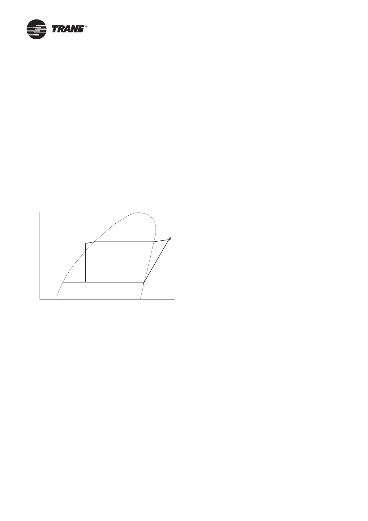
Refrigerant Cycle
Typical refrigerant cycle on the RTAF is represented on
the pressure enthalpy diagram shown in the fi gure below.
Key state points are indicated on the fi gure. The cycle for
the full load design point is represented in the plot.
Figure 21 – Pressure enthalpy (P-h) diagram
The RTAF chiller uses a shell and tube evaporator design
with refrigerant evaporating on the shell side and water
fl owing inside tubes having enhanced surfaces (states
4 to 1). The suction lines are designed to minimize
pressure drop (states 1 to 1b) the compressor is a twin-
rotor helical rotary compressor designed similarly to the
compressors offered in other Trane screw compressor
based chiller (states 1b to 2). The discharge lines include a
highly effi cient oil separation system that removes 99,8%
of the oil from the refrigerant stream going to the heat
exchangers (states 2 to 2b). De-superheating, condensing
and sub-cooling are accomplished in a microchannel
cooled heat exchanger where refrigerant is condensed
inside the microchannel (states 2b to 3b). Refrigerant
fl ow through the system is balanced by an electronic
expansion valve (states 3b to 4).
Refrigerant and Oil
RTAF use R134a, Trane believes that responsible
refrigerant practices are important to the environment,
our customers, and the air conditioning industry. All
technicians who handle refrigerants must be properly
qualifi ed. All local and UE regulations in what handling,
reclaiming, recovering and recycling, must be followed.
R134a is a medium pressure refrigerant. It may not be
used in any condition that would cause the chiller to
operate in vacuum without a purge system. RTAF is not
equipped with a purge system. Therefore RTAF must
not be operated in a condition that would result in a
saturated condition in the chiller of -26°C or lower. R134a
requires the use of specifi c POE oils as designated on
the unit nameplate. Use only R134a, Trane Oil 00048E in
RTAF SE HE and XE chillers and Trane OIL 00317 in RTAF
HSE chillers.
Compressor and Lube Oil System
The rotary screw compressor is semi-hermetic, direct
drive with capacity control via a slide valve on SE, HE
and XE versions and combined action of slide valve and
variable frequency driver on the HSE version.
The motor is a suction gas cooled hermetically sealed,
induction squirrel cage motor. Oil separator is provided
separately from the compressor. Check valve in the
compressor discharge and lube oil system are also
provided.
Condenser and Fans
The air cooled Microchannel condenser coils use all
aluminum brazed fi n construction.
The coil is composed of three components: the fl at
microchannel tube, the fi ns located between the
microchannel tubes, and two refrigerant manifolds. Coils
can be cleaned with high pressure water (see Condenser
Coils MCHE maintenance for instructions).
The condenser coil has an integral subcooling circuit. The
maximum allowable working pressure of the condenser
is 25.0 bars. Condensers are factory proof and leak
tested at 45 bars.
Direct-drive vertical-discharge airfoil condenser fans are
dynamically balanced.
Standard units will start and operate from -10°C to 46°C
ambient and with low ambient option temperature down
to -20°C. With high ambient option units can run from
-10°C up to 55°C.
Evaporator
The evaporator is a shell and tube heat exchanger design
constructed from carbon steel shells and tube sheets
with internally and externally fi nned seamless copper
tubes mechanically expanded into the tube sheets. Tubes
are cleanable with dismountable water boxes. Tubes
diameter exterior is 19mm. Each tube is individually
replaceable.
The evaporator is designed, tested and stamped in
accordance with PED 97/23/CE Pressure Vessel Code
for a refrigerant side working pressure of 14 bars. The
evaporator is designed for a water side working pressure
of 10.5 Bar. Standard water connections are grooved for
Victaulic style pipe couplings. Water boxes are available
in 2 passes confi gurations and include an air vent,
a drain and fi ttings for temperature control sensors.
Evaporator is insulated with closed cell insulation of
19mm thickness and K factor of 0,035 W/m²°K.
R-134a
h (btu/lb)
P (psia)
1
1b
2
2b
3
3b
4
120 1
10 0806040200
30
50
10 0
200
500
600
 Loading...


