RLC-SVX19A-E4
23
Evaporator Piping
Evaporator Piping Components
Piping components include all devices and controls used to provide proper water system operation and unit
operating safety. A typical RTAF evaporator piping is shown below.
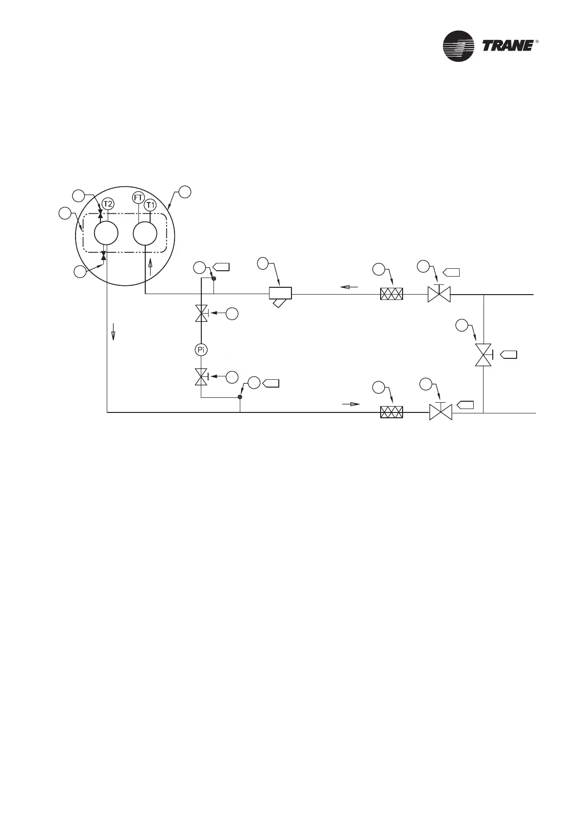
Figure 6 – Typical RTAF evaporator water piping
1 = Bypass valve
2 = Isolation valve
3 = Vibration isolators
4 = Evaporator – End view (2-pass)
5 = Evaporator Waterbox
6 = Vent
7 = Strainer
8 = Drain
Entering Chilled Water Piping
• Air vents to bleed the air from the system (to be placed
on the highest point)
• Water pressure gauges with shutoff valves
• Vibration eliminators
• Shutoff (isolation) valves
• Thermometers if desired (temperature readings
available on chiller controller display)
• Clean-out tees
• Pipe strainer
Pi = Pressure gauge
FT = Water Flow Switch
T1 = Evaporator Water Inlet Temperature Sensor
T2 = Evaporator Water Outlet Temperature Sensor
A = Isolate unit for initial water loop cleaning
B = Vent must be installed at the high point of the line
C = Drain must be installed at the low point of the line
Leaving Chilled Water Piping
• Air vents to bleed the air from the system (to be placed
on the highest point)
• Water pressure gauges with shut off valves
• Vibration eliminators
• Shutoff (isolation) valves
• Thermometers (temperature readings available on the
chiller controller display)
• Clean-out tees
• Balancing valve
A
2
1
2
3
3
7
8
6
4
5
2
2
A
A
B
8
C