Diagnostics and Troubleshooting
UNT-SVX07J-EN 131
Wireless Zone Sensors (WZS)
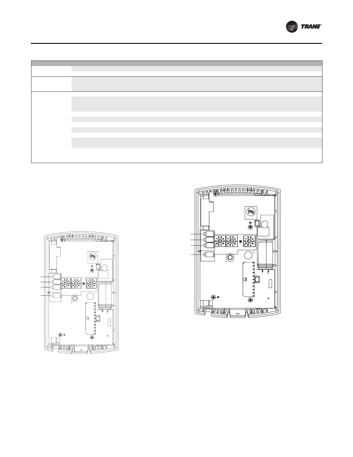
The receiver for all models has four LEDs: LED1, LED2,
LED3, and LED5. Figure below shows their locations.
Note: To view LEDs on a flush mount receiver on a fan coil
unit, the front panel of the unit must be removed.
The sensor for a wireless zone sensor (WZS) has four
LEDs: LED1, LED2, LED3, and LED5 and a test button.
Figure below shows their locations.
The sensor for a wireless display sensor (WDS) has test
symbols and error codes that appear on the display, and a
test button. See the figure below.
Excess dirt in unit
Missing filters Replace filters
Filter bypass Reduce filter bypass by ensuring all blockoffs are in place.
Microbial growth
(mold) inside air
handler
Standing water in drain pan See “Standing water in drain pan” above
Low refrigerant coil
capacity
Incorrect airflow Check fan operating condition.
Expansion valve is not operating properly or is sized
incorrectly
Check sensing bulb temperature.
Verify valve operation.
Verify proper valve size.
Incorrect refrigerant charge Verify refrigerant charge and adjust if necessary.
Condensing unit failure Verify condensing unit operation.
Coil is piped incorrectly Verify coil piping (see “Coil Piping and Connections,” p. 53.)
Clogged refrigerant line filter Change filter core.
Failure of suction/liquid line components Verify component operation
Dirty fin surface
Clean the fin surface.
Do not use steam to clean refrigerant coils.
Fin frosting
Verify defrost cycle operation.
Verify frostat operation.
Verify refrigerant charge.
Table 62. Fan coil and cabinet heater troubleshooting recommendations
Symptom Probable Cause Recommended Action
Figure 108. Receiver for all fan coil models showing LED
locations
HEATING SET
FAN/SYSTEM
SETPOINT
ZONE
GND-SIGNAL
24VAC/DC
GND-POWER
COMM +
COMM -
S5
POWER
LED5
LED1
LED2
LED3
SIGNAL
ADDRESS
S1 S2
S3
J1
C33
S4
LED4
WIRELESS
INSTALL
J2
1
C34
C35
R77
Pb-FREE
LED1
LED2
LED3
LED5
Figure 109. WZS showing LED locations and test button
HEATING SET
FAN/SYSTEM
SETPOINT
ZONE
GND-SIGNAL
24VAC/DC
GND-POWER
COMM +
COMM -
S5
POWER
LED5
LED1
LED2
LED3
SIGNAL
ADDRESS
S1 S2
S3
J1
C33
S4
LED4
WIRELESS
INSTALL
J2
1
C34
C35
R77
Pb-FREE
LED1
LED2
LED3
LED5
 Loading...