UNT-SVX07J-EN 5
Model Number Descriptions
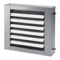
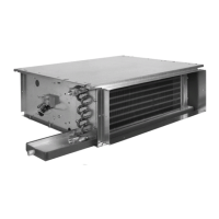
UniTrane™ Fan Coil/
Force Flo™ Cabinet
Heater
Following is a complete description of
the UniTrane fan coil and Force Flo
cabinet heater model number. Each digit
in the model number has a
corresponding code that identifies
specific unit options.
Note: Not all options are available on all
cabinet styles. Contact your local
Trane sales representative for
more information.
Digits 1, 2 — Unit Type
FC = Fan Coil
FF = Force Flo
Digit 3 — Model
A = Vertical concealed
B = Vertical cabinet
C = Horizontal concealed
D = Horizontal cabinet
E = Horizontal recessed
F = Vertical Wall-hung
H = Vertical recessed
J = Vertical slope-top
M = Inverted vertical cabinet
N = Inverted vertical recessed
P = Compact concealed
Digit 4 — Development
Sequence
B = Development B
Digits 5, 6, 7 — Unit Cabinet
Size
020= 200 cfm
030= 300 cfm
040= 400 cfm
060= 600 cfm
080= 800 cfm
100 = 1000 cfm
120 = 1200 cfm
Digit 8 — Unit Voltage
1 = 115 V/60 Hz/1 PH
2 = 208 V/60 Hz/1 PH
3 = 277 V/60 Hz/1 PH
4 = 230 V/60 Hz/1 PH
5 = 208 V/60 Hz/3 PH
6 = 230 V/60 Hz/3 PH
7 = 480 V/60 Hz/3 PH
8 = 115 V/50 Hz/1 PH (SOS ONLY)
9 = 220-240 V/50 Hz/1 PH
A = 220-240 V/50 Hz/3 PH
B = 380-415 V/50 Hz/3 PH
Digit 9 — Piping System /
Placement
A = Without pipe, RH, Without
auxiliary
B = Without pipe, LH, Without
auxiliary
C = Without pipe, RH, With auxiliary
D = Without pipe, LH, With auxiliary
E = Without pipe, RH, Without
auxiliary, Extended end
F = Without pipe, LH, Without
auxiliary, Extended end
G = Without pipe, RH, With auxiliary,
Extended end
H = Without pipe, LH, With auxiliary,
Extended end
J = With pipe, RH
K = With pipe, LH
L = With pipe, RH, Extended end
M = With pipe, LH, Extended end
N = Without pipe, RH, With auxiliary,
Extended end pipe and control
side
P = Without pipe, LH, With auxiliary,
Extended end pipe and control
side
Q = With pipe, RH, With auxiliary,
Extended end pipe and control
side
R = With pipe, LH, With auxiliary,
Extended end pipe and control
side
Digits 10, 11 — Design
Sequence
***= Factory assigned
AW = AW design
Digit 12 — Inlet Style
A = Front toe space
B = Front bar grille
C = Front stamped louver
D = Bottom stamped louver
E = Bottom toe space
F = Back duct collar
G = Back exposed fan
H = Back stamped louver
J = Top duct collar
K = Exposed fan
L = Bottom filter
Digit 13 — Outside Air Damper
0=None
A = Manual, Bottom opening
B = Manual, Back opening
C = Manual, Top opening
D = Auto, 2-position, Bottom
opening
E = Auto, 2-position, Back opening
F = Auto, 2-position, Top opening
G = Economizer, Bottom
opening
H = Economizer, Back opening
J = Auto, Economizer, Top opening
K = No damp, Bottom opening
L = No damp, Back opening
M = No damp, Top opening
Digit 14 — Outlets Style
A = Front duct collar
B = Front bar grille
C = Front stamped louver
D = Front quad grille
E = Bottom duct collar
F = Bottom stamped louver
G = Top quad grille
H = Top bar grille
J = Top duct collar
K = Bottom bar grille
Digit 15 — Paint Cabinet Color
0 = None (Not painted unit)
1 = Deluxe beige
2=Soft dove
3=Cameo white
4 = Driftwood grey
5 = Stone grey
6=Rose mauve
Digit 16 — Tamperproof Locks /
Leveling Feet
0=None
A = Locking panel
B = Keylock access door
C = Locking panel, Keylock access
door, Secure grille
D = Leveling feet
E = Locking panel with
leveling feet
F = Keylock door with
level feet
G = Locking panel, Key access door,
Secure grille, Leveling feet
Digit 17 — Motor Types
A = Free discharge
B = High static
Digit 18 — Main Coil
A = 2-row cooling/heating
B = 3-row cooling/heating
C = 4-row cooling/heating
D = 2-row cooling, 1-row heating
E = 2-row cooling, 2-row heating
F = 3-row cooling, 1-row heating
G = 2-row cooling only or heating
only
H = 3-row cooling only or heating
only
J = 4-row cooling only or heating
only
K = 2-row cooling/heating, Electric
heat
L = 3-row cooling/heating, Electric
heat
M = 4-row cooling/heating, Electric
heat
N = Electric heat only, 1 stage
P = 2-row cooling/heating, 1-row
heating
Q = 2-row cooling/heating, 2-row
heating
R = 3-row cooling/heating, 1-row
heating
U = Electric heat only, 2 stage
V = Electric heat, Low kW, 1 stage
W = Steam coil
X = 2-row cooling only, Electric
heat
Y = 3-row cooling only, Electric
heat
Z = 4-row cooling only, Electric
heat
1 = 3-row cooling, 1-row heating
with high capacity
2 = 3-row cooling/
heating, 1-row heating with high
capacity
3 = Heat pump
 Loading...


