Startup
106 UNT-SVX07J-EN
The fan runs continuous when placed in the high, medium,
or low position. Use Rover, Trane’s installation and service
tool, to change auto defaults.
When the heating output is controlled off, the controller
automatically controls the fan on for an additional 30
seconds. This delay allows the fan to dissipate any residual
heat from the heating source, such as electric heat.
Tracer® ZN520 Controllers
Tracer® ZN520 controller is a discrete speed controller that
can be used in a stand-alone application or can
communicate with a building automation system using
LonTalk Communication.
ZN520 Stand-Alone Operation
The factory pre-programs the Tracer® ZN520 with default
values to control the temperature and unit airflow. Use
Tracer® Summit building automation system or Rover™
software to change the default values. For more
information, refer to:
• CNT-SVX04*-EN Tracer® ZN520 Unit Controller
Installation, Operation, and Programming Guide
Follow the procedure below to operate the Tracer® ZN520
in a stand-alone operation:
1. Turn power on at the disconnect switch option.
2. Position the fan mode switch to either high, medium,
low, or the auto position.
3. Rotate the setpoint dial on the zone sensor module to
55°F for cooling or 85°F for heating.
The appropriate control valve will actuate assuming the
following conditions:
• Room temperature should be greater than 55°F and
less than 85°F.
• For a 2-pipe fan-coil unit with an entering water
temperature sensor, the water temperature input is
appropriate for the demand placed on the unit. For
example, cooling operation is requested and cold
water (5° lower than room temperature) flows into the
unit.
• Select the correct temperature setpoint.
Note: Select and enable zone sensor temperature
settings to prevent freeze damage to unit.
ZN520 Operation
Fan Mode Switch
Off - Fan is turned off, two-position damper option spring-
returns closed.
Hi, Med, Low - Fan runs continuously at the selected
speed. The two-position damper option opens to an
adjustable mechanical stop position.
Controller
Off - Fan is off; control valves and fresh air damper option
close. Low air temperature detection option is still active.
Auto - Fan speed control in the auto setting allows the
modulating (3-wire floating point) or 2–position control
valve option and three-speed fan to work cooperatively to
meet precise capacity requirement, while minimizing fan
speed (motor/energy/acoustics) and valve position (pump
energy, chilled water reset). As the capacity requirement
increases at low fan speed, the water valve opens. When
the low fan speed capacity switch point is reached, the fan
switches to medium speed and the water valve repositions
to maintain an equivalent capacity. The reverse sequence
takes place with a decrease in required capacity.
Low/Med/High (Continuous Fan) - Fan operates
continuously while control valve option cycles to maintain
setpoint temperature.
Sequence of Operation
Occupancy Modes
The controller operates the fan in the following modes:
• Occupied
• Unoccupied
• Occupied standby
• Occupied bypass
• Tracer® Summit™ with supply fan control
Occupied
When the controller is in the occupied mode, the unit
attempts to maintain the space temperature at the active
occupied heating or cooling setpoint, based on the
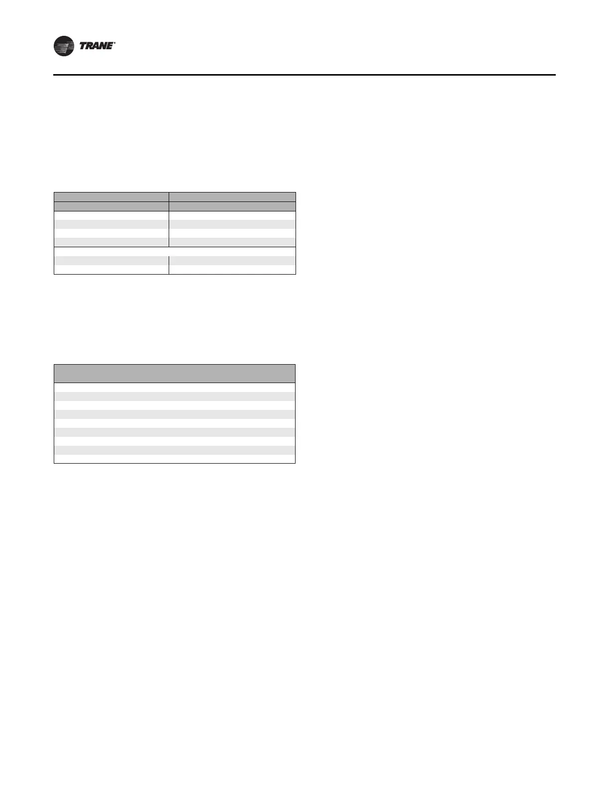
Table 47. Fan mode operation
Heating Mode Cooling Mode
Fan mode Occupied Unoccupied Occupied
Off Off Off Off
Low Low Off/high
(a)
(a) Whenever two states are listed for the fan:
The first state (off) applies when there is not a call for heating or cooling.
The second state (varies) applies when there is a call for heating or
cooling.
The heat default is factory configured for low fan speed, and the cool
default is medium.
Low
Medium Medium Off/high
(a)
Medium
High High Off/high
(a)
High
Auto
Continuous Heat default Off/high
(a)
Cool default
Cycling off/heat default Off/high
(a)
Off/cool default
Table 48. Valid operating range and factory default
setpoints
Setpoint/
parameter
Default
Setting
Valid Operating
Range
Unoccupied cooling setpoint 85°F 40°F to 115°F
Occupied cooling setpoint 74°F 40°F to 115°F
Occupied heating setpoint 71°F 40°F to 115°F
Unoccupied heating setpoint 60°F 40°F to 115°F
Cooling setpoint high limit 110°F 40°F to 115°F
Cooling setpoint low limit 40°F 40°F to 115°F
Heating setpoint high limit 105°F 40°F to 115°F
Heating setpoint low limit 40°F 40°F to 115°F
Power-up control wait 0 sec 0 sec to 240 sec
 Loading...