Diagnostics and Troubleshooting
138 UNT-SVX07J-EN
Red Service LED The red LED normally indicates if the
unit controller is operating properly or not. Refer to the
table below.
Note: If the service push button is held down for more
than 15 seconds, the Tracer® controller will
uninstall itself from the ICS communication
network and shut down all unit operation. This
mode is indicated by the red Service LED flashing
once every second. See the Red Service LED
section. Use the Rover service tool to restore the
unit to normal operation. Refer to the service tool
product literature for more information
Manual Output Test
The purpose of the manual output test sequence for
Tracer
®
ZN010, ZN510, and ZN520 controllers is to verify
output and end device operation. Use the manual output
test to:
• Verify output wiring and operation without using
Rover, service tool
• Force the water valve to open and balance the hydronic
system
Note: The manual output test is not an automatic cycle.
You must press the TEST button to proceed
through each step.
The controller observes all diagnostics that occur during
the test sequence. Although an automatic diagnostic reset
sequence exists as part of the controller’s normal
operation, the automatic diagnostic reset feature is not
active during the test sequence.
If left in an individual test step, the controller remains in
test mode for 60 minutes and then exits to normal
operation.
Many service calls are due to unit diagnostics. The test
sequence resets unit diagnostics and attempts to restore
normal unit operation prior to testing the outputs. If the
diagnostics remain after a reset, the STATUS LED indicates
the diagnostic condition is still present (two blinks).
Manual Output Test Procedure
Follow the procedure below to test Tracer® ZN010, ZN510,
and ZN520 controllers.
1. Press and hold the TEST button for at least two
seconds (not exceeding 5 seconds), and then release,
to start the test mode.
2. The test sequence will turn off all outputs and then
attempt to clear all diagnostics.
3. Press the TEST button several more times (no more
than once per second) to advance through the test
sequence.
The outputs are not subject to minimum times during the
test sequence. However, the test sequence only permits
one step per second which limits minimum output time.
The green LED is turned off when the TEST button is
pressed. To begin the manual output test mode, press and
hold the TEST button (turning off the green LED) for at least
two seconds.The green LED will begin to blink, indicating
the controller is in test mode. See the table below.
Table 74. Red service LED activity for Tracer® ZN010,
ZN510, or ZN520 controllers
LED Activity Description
Off continuously after power is
applied to the controller.
Normal operation
On continuously, even when
power is first applied to the
controller.
Someone is pressing the Service
button or the controller has failed.
LED flashes about once every
second.
Uninstall (normal controller mode).
To restore normal operation, use the
Rover service tool.
Black Service push button.
Use the Service button to install the
Tracer®
ZN520 controller in a
communication network.
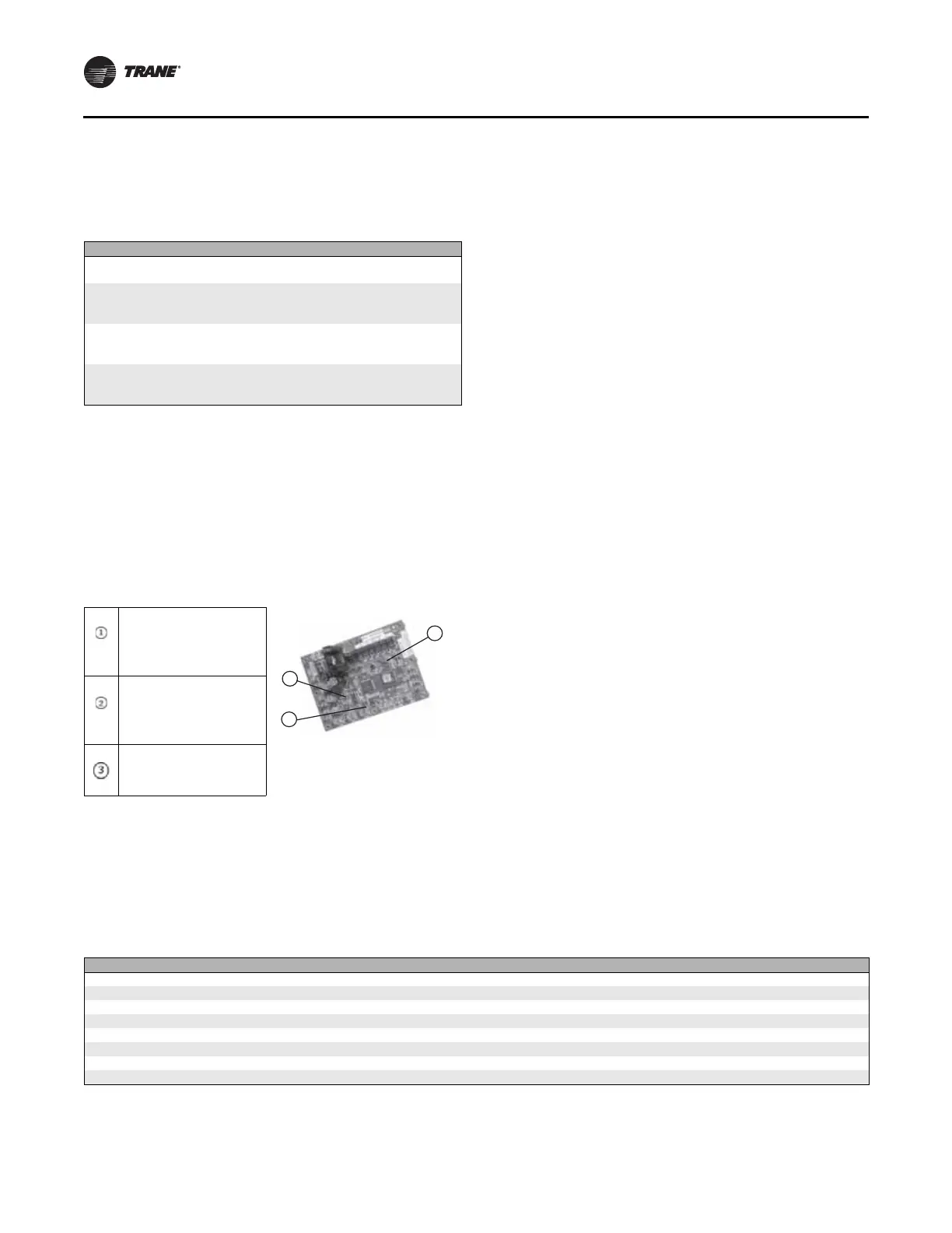
Figure 111. LED light status on ZN520 controller
Green STATUS LED
Indicates whether the
controller is powered
on (24 Vac supplied)
Yellow COMM LED
Indicates if
communication is
functioning
Red SERVICE LED
Indicates if service is
needed
Table 75. Test sequence for 1-heat/1-cool configurations for Tracer® ZN010, ZN510, and ZN520
Steps Fan BOP1-3 Cool Output BOP4
1
Heat Output BOP5 Damper BOP6
1. Off Off Off Off Closed
2. Fan High High Off
2
Off Closed
3. Fan Medium Medium Off Off Closed
4. Fan Low Low Off Off Closed
5. Cool High On Off Closed
6. Heat High Off On Closed
7. Fresh Air Damper High Off Off Open
3
8. Exit 4
Notes:
1
For all 1-heat/1-cool applications including 2-pipe changeover, BOP4 energizes in the cooling test stage and BOP5 energizes in the heat test
stage.This occurs even though during normal 2-pipe changeover operation BOP4 controls the unit valve for both cooling and heating.
2
At the beginning of the Fan High step, the controller attempts to clear all diagnostics
3
The fresh air damper (BOP6) only energizes during this step if binary output 6 has been configured as a fresh air damper.
4
After the Fresh Air Damper step, the test sequence performs the Exit step.This initiates a reset and attempts to return the controller to normal
operation
 Loading...