EasyManua.ls Logo

Trane UniTrane User Manual

Trane UniTrane
164 pages
To Next Page IconTo Next Page
To Previous Page IconTo Previous Page
Page #70 background imageLoading...
Page #70 background image
ECM Overview and Setup
70 UNT-SVX07J-EN
Configuration Examples
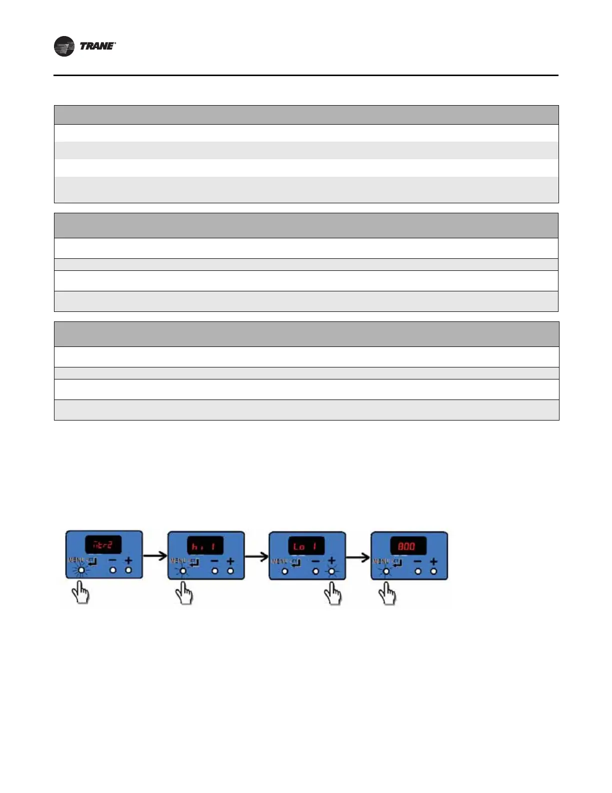
Example 1
To view the value of parameters without saving. In this
case we wish to verify that the “Low Speed Value” for
Motor 1 is set correctly to 800 rpm.
We start with the motor control board scrolling status
display and proceed as follows:
Example 2
We wish to change the change the value of Low Speed to
820 rpm:
We will continue from the previous example as shown
below, using a long press to “save” the new desired value.
If the display has timed out and returned to the status loop,
repeat Example 1 to arrive back at this example’s starting
point.
Table 36. Button actuation levels
Button
Menu/Set
Duration Action
Short Press in
Status Display
<1 sec None
Short Press in Configuration Display
Toggles between parameter name and value without saving
(abandons value if changed).
Long Press/Hold
in Status Display
>3 sec Enters the configuration menu
Long Press/Hold
in Configuration Display
>3 sec
If on a parameter name, toggles to the value. If on a parameter value,
saves the value settings and returns to the parameter name as
confirmation.
Button
Decrement
Duration Action
Short Press in
Status Display
<1 sec None
Short Press in Configuration Display <1 sec Scrolls through parameter names, or decreases value of parameter.
Long Press/Hold
in Status Display
>3 sec n/a
Long Press/Hold
in Configuration Display
>3 sec
Faster scroll through parameter name, or faster decrease of values of
parameters.
Button
Increment
Duration Action
Short Press in
Status Display
<1 sec None
Short Press in Configuration Display <1 sec Scrolls through parameter names, or increases value of parameter.
Long Press/Hold
in Status Display
>3 sec n/a
Long Press/Hold
in Configuration Display
Faster scroll through parameter name, or faster increase of values of
parameters.
Figure 48. Verify low speed value

Table of Contents

Other manuals for Trane UniTrane

Questions and Answers:

Trane UniTrane Specifications

General IconGeneral
Voltage208V, 240V, 480V (depends on model)
EfficiencyVaries by model. Consult specific product data.
Control OptionsThermostat
AirflowVaries by model. Consult specific product data.
DimensionsVaries by model. Consult specific product data.
WeightVaries by model. Consult specific product data.

Summary

SAFETY WARNING

Proper Field Wiring and Grounding Required

Personal Protective Equipment (PPE) Required

Follow EHS Policies!

Pre-Installation

Installation—Mechanical

Installation Checklist

Abbreviated guide to detailed mechanical installation procedures.

Installing the Unit

Procedures for properly installing the unit.

Duct Connections

Coil Piping and Connections

Installation - Electrical

Supply Power Wiring

Guidelines for sizing and connecting power supply wiring.

ECM Overview and Setup

Overview

Introduction to the Trane ECM motor and VelociTach control board.

Installation and Initial Setup

Procedures for installing and setting up ECM units.

VelociTach Motor Control Board

Details on the VelociTach motor control board functions and interface.

Motor Control Board Settings

Reference for motor control board parameter names and typical settings.

Installation - Controls

Power Supply Requirements

Critical requirements for controller power supply.

Zone Sensor Options

Zone Sensor Installation

Guidelines for installing zone sensors.

Zone Sensor Settings

Procedures for configuring zone sensors.

Startup

Pre-Startup Checklist

Checklist for verifying installation before unit startup.

Unit Startup

Procedures for starting the unit and controllers.

Routine Maintenance

Diagnostics and Troubleshooting

ECM Motors Troubleshooting

Troubleshooting common issues with ECM motors.

Wiring Diagrams

Typical Wiring Diagram for ZN010 Unit

Wiring diagram for ZN010 unit with single-stage electric heat.

Typical Wiring Diagram for UC400-B Unit

Wiring diagram for UC400-B unit with dual-stage electric heat.

Typical Wiring Diagram for CSTI Unit

Wiring diagram for CSTI unit with 3-phase single-stage electric heat.

Typical Wiring Diagram ZN520 Unit

Wiring diagram for ZN520 unit with dual-stage electric heat.

Typical Wiring Diagram for Tracer® ZN520 Unit

Wiring diagram for ZN520 unit with four-pipe configuration.

Typical Wiring Diagram for Tracer® ZN510 Unit

Wiring diagram for ZN510 unit with four-pipe configuration.

Typical Wiring for UC400-B Controller with WCI

Wiring diagram for UC400-B controller with WCI.

Related product manuals