Installation - Controllers
86 UNT-SVX07J-EN
of cooling or heating. The zone sensor module is capable
of transmitting the following information to the controller:
• Timed override on/cancel request
• Zone setpoint
• Current zone temperature
• Fan mode selection (off-auto-high-med-low)
For optimal system performance, units can operate as part
of a Tracer® SC building automation system. The
controller is linked directly to the Tracer® SC via a twisted
pair communication wire, requiring no additional
interface device (i.e., a command unit). The Tracer®
control system can monitor or override Tracer® UC400-B
control points.This includes such points as temperature
and output positions.
Note: For more detailed information, refer to:
• BAS-SVX20C-EN Tracer® UC400-B Programmable
Controller Installation, Operation, and Maintenance
manual
Communication Wire Specifications
All wiring must comply with the National Electrical Code
(NEC™) and local electrical codes.
Field-supplied BACnet MS/TP link wiring must be installed
in compliance with NEC and local codes. The wire must be
low-capacitance, 18-gauge, stranded, tinned-copper,
shielded, twisted-pair.
Note: For more details, refer to Wiring Guide: Unit
Controller Wiring for the Tracer® SC™ System
Controller (BAS-SVN03D-EN, or the most recent
revision).
General Wiring Guidelines
To connect wires to the UC400-B controller or the
expansion modules:
1. Strip the wires to expose 0.28 inch (7 mm) of bare wire.
2. Insert the wire into a terminal connector.
3. Tighten the terminal screw to 0.5 to 0.6 N-m (71 to
85 ozf-in or 4.4 to 5.3 lbf-in.).
4. Tug on the wires after tightening the screws to ensure
all wires are secure as shown on the right.
Setting the Address
The rotary address dials on the UC400-B controller serve
one or two purposes depending upon the network: they
are always used for the MAC Address, which is sometimes
all or part of the BACnet Device ID.
Use a 1/8 inch (3.2 mm) flathead screwdriver to set rotary
address dials. Dials rotate in either direction.
MAC Address
The MAC Address is required by the RS-485
communication protocol on which BACnet operates. A
UC400-B controller can use a MAC Address from 001 to
120.
Important: Each device on the link must have a unique
MAC Address/Device ID. The controller
rotary addresses should be sequentially set,
with no gaps in the numbering, starting with
001 on each link (for example 001, 002, 003,
004 and so on). A duplicate address or a 000
address setting will interrupt
communications and cause the Tracer® SC
device installation process to fail.
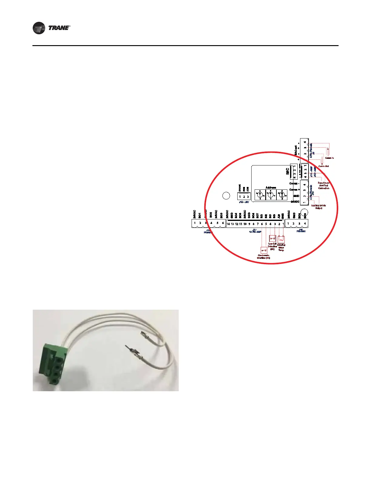
Figure 64. Connecting wires to terminal
Figure 65. Setting rotary address dials
1 4 P in AMP
B
O
4
B
O
5
24
V
A
C
G
N
D
B
O
6
B
O
7
BI2
B
I
2
B
I
3
B
I
3
A
I
5
G
N
D
24
V
A
C
G
N
D
14 1
3
12 11 1
0
9
8
7
6 5
4
3
2 1
J
1
8
B
O
7
24
V
A
C
J
1 4 -
J S
T
B
O
6
0
5
3
8
0
5
3
8
1
5
3
8
0
1
5
3
8
0
A
dd
r
es s
4 P in Ph
oe
nix
J
1
7
B
O
9
G
N
D
24
V
A
C
B
O
8
J
1
6
B
O
1
24
V
A
C
B
O
2
24
V
A
C
B
O
3
24
V
A
C
P h
oe
nix
P h
oe
nix
24
V
D
C
G
N
D
C
o
mm +
C
o
mm -
J
8
BA
C
n
e
t
4
Pi
n
P
h
oe
n
i
x
J
1
3
+ - + -
IM
C
J
1 2 - AMP
J
11 - AMP
+
-
G
n
d
24
V
D
C
1 2
3
4
5
6
1
2
3
4
1
2
3
4
1
2
3
4
1
2
3
4
1
2
3
4
1 2
3
En
t
e
rin
g
W
a
t
e
r
T
e
m
p
C
o
mm In
C
o
mm
O
u
t
A
u
xili
a
r
y
24
V
dc
O
u
t
p
u
t
Z
o
n
e
S
e
n
so
r
S
e
r
v
T
oo
l
C
o
nn
ec
t
i
o
n
L
ow
C
o
il
D
e
t
ec
t
i
o
n
(
N
C
)
C
o
n
de
n
s
a
t
e
O
ve
r
ow
(
N
C
)
 Loading...