Installation - Controllers
88 UNT-SVX07J-EN
Important: If the polarity is inadvertently reversed
between two controllers powered by the
same transformer, a difference of 24Vac will
occur between the grounds of each
controller, which can result in:
• Partial or full loss of communication on
the entire BACnet MS/TP link
• Improper function of the UC400-B
controller outputs
• Damage to the transformer or a blown
transformer fuse
Transformer Recommendations
A 24Vac power supply must be used for proper operation
of the binary inputs, which requires 24Vac detection. In
addition, the spare 24Vac outputs may be used to power
relays and TRIACS.
• AC transformer requirements: UL listed, Class 2 power
transformer, 24Vac ±15%, device max load 24VA. The
transformer must be sized to provide adequate power
to the controller (12VA) and outputs (maximum 12VA
per binary output).
• CE-compliant installations: The transformer must be
CE marked and SELV compliant per IEC standards.
Wiring Requirements
To ensure proper operation of the UC400-B controller,
install the power supply circuit in accordance with the
following guidelines:
• A dedicated power circuit disconnect switch must be
near the controller, easily accessible by the operator,
and marked as the disconnecting device for the
controller.
• 18 AWG (0.823 mm
2
) copper wire is recommended for
the circuit between the transformer and the controller.
Important: The controller must receive AC power from
a dedicated power circuit; failure to comply
may cause the controller to malfunction. DO
NOT run AC power wires in the same wire
bundle with input/output wires; failure to
comply may cause the controller to
malfunction due to electrical noise.
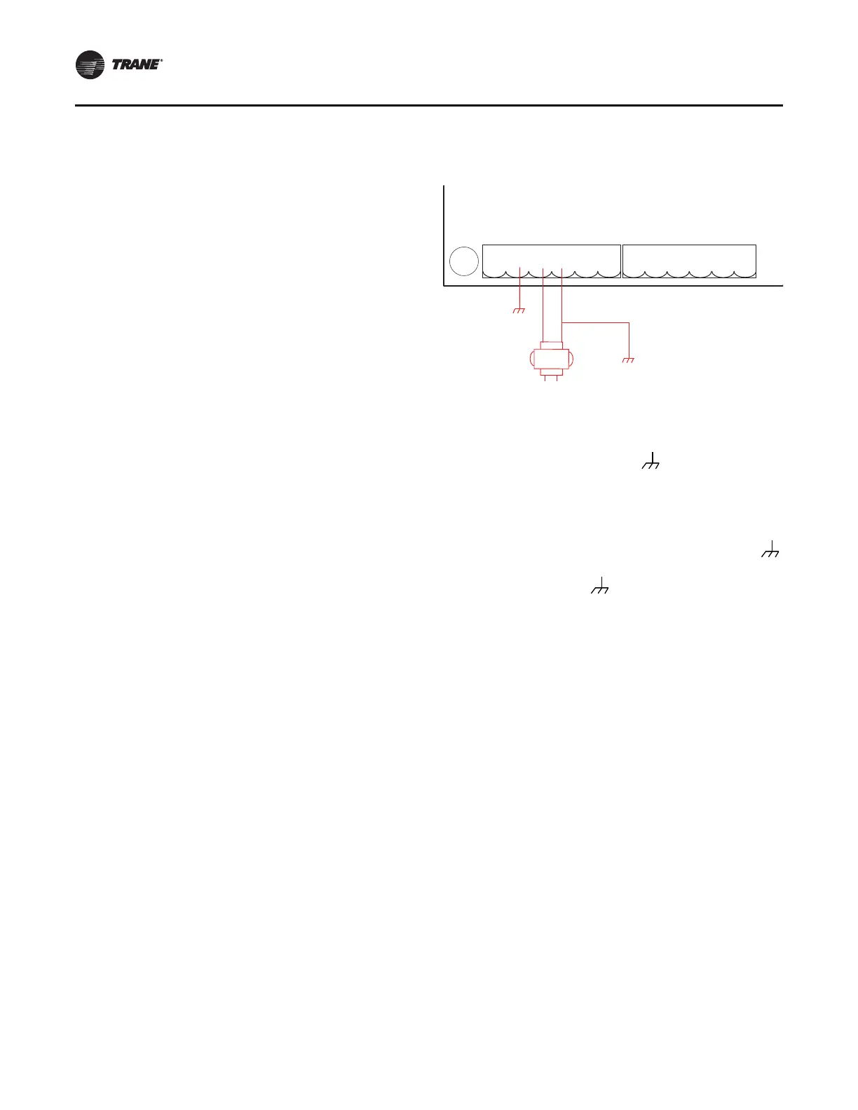
Connecting Wires
To connect the wires:
1. Disconnect power to the transformer.
2. Connect the 24Vac secondary wires from the
transformer to the 24Vac and terminals on the
UC400-B controller (refer to the illustration below).
3. Do one of the following to ensure the controller is
adequately grounded:
• Connect a grounding pigtail at some point along the
secondary wire that runs between the controller
terminal and the transformer.
• Ground one of the terminals on the controller to
the enclosure (if the enclosure is adequately
grounded) or to an alternate earth ground.
Note: A pigtail connection may be necessary between
earth ground and/or enclosure ground if the device
is not grounded through one leg of the transformer
wiring.
.
Power ON Check
To perform a Power ON check:
1. Verify that the 24Vac connector and the chassis ground
are properly wired.
2. Remove the lockout/tagout from the line voltage power
to the electrical cabinet.
3. Energize the transformer to apply power to the UC400-
B controller.
4. Observe the UC400-B controller when power is applied
to verify the power check sequence as follows:
a. The power LED lights red for 1 second
b. The power LED lights green
• If the sequence above is completed as described,
the controller is properly booted and ready for the
application code.
If the power LED flashes red, a fault condition exists.
Figure 68. Grounding the controller
24VAC
G
N
D
24VAC
G
ND
2
4
VA
C
GND
J15 J16
BO1
24VAC
BO2
2
4VAC
BO3
24VAC
PhoenixPhoenix
1 2 3 4 5 6 1 2 3 4 5 6
Alternate
Ground
Method
24 Vac
Transformer
 Loading...