16 VAV-SVX01C-EN
UCM 4.2 Installation and Wiring
2. The maximum wire length should not exceed 5,000 feet (1,524 m).
3. Communication link wiring cannot pass between buildings.
4. A maximum of 63 UCMs can be connected to each COM Link. Daisy chaining is a typical
configuration. “STAR” chaining is also acceptable.
Note: Polarity is extremely important and must be observed on communication link connections.
5. At the VAV box, communication link wires must be connected to TB2-1, 3 (+) and TB2-2, 4 (-)
terminals on the UCM.
6. Verify that the UCM address is properly set (DIP switch SW1). See Tab l e 6, p . 16 for proper DIP
switch settings.
DIP Switch Settings
DIP Switch SW1 contains six switches for addressing the UCM. These switches allow a user to set
a unique communication address for each UCM. Each UCM on a given communication link must
have a unique address in order for Tracer Summit or the CCP to communicate to it. Refer to Tab le 6,
p. 16 for UCM 4.2 DIP switch settings.
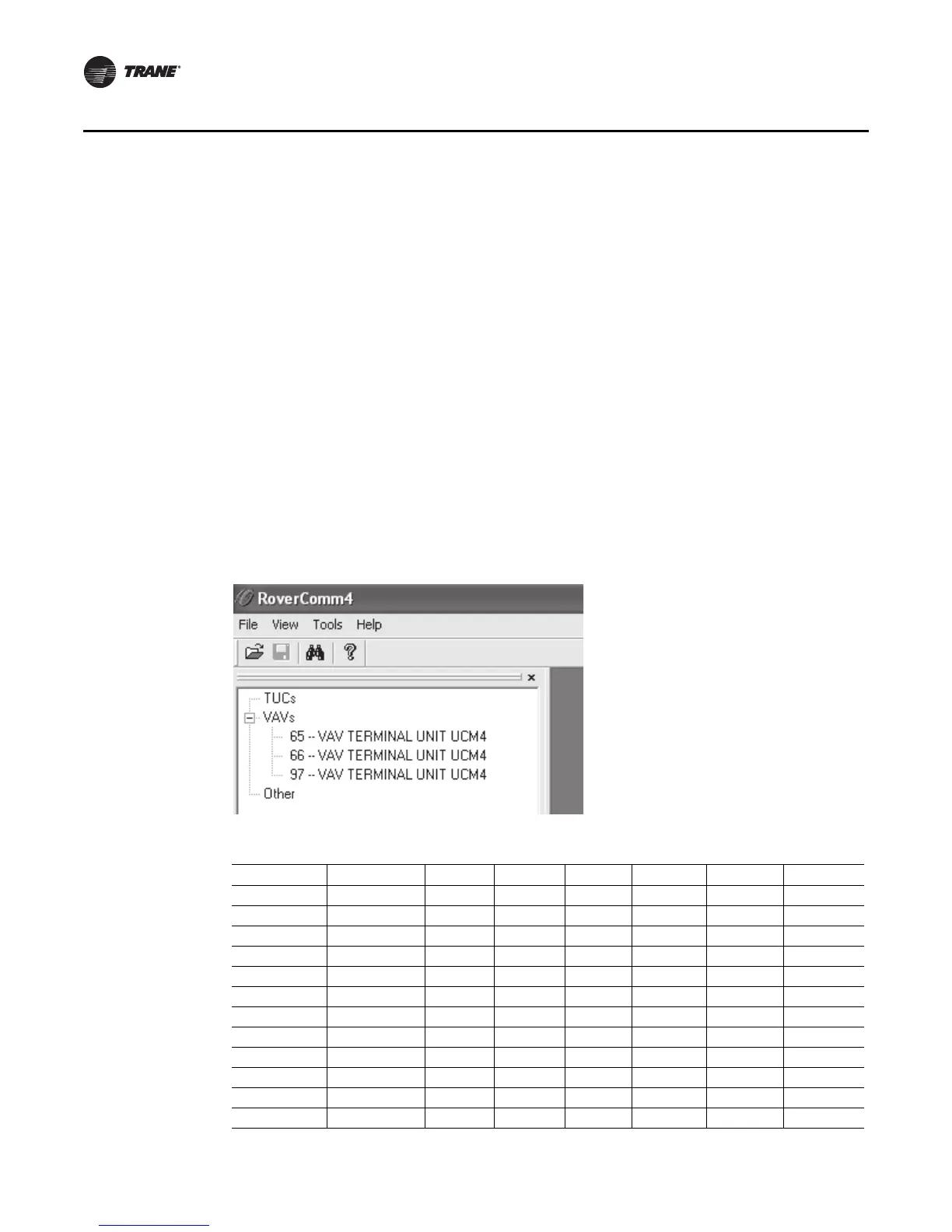
Note: When using Rover™ service tool to communicate to the UCM, you must add 64 to the DIP
switch address. For example, a UCM with the DIP switch address set to 1 would be UCM
Number 65 in Rover.
Figure 2. Rover screen/application
Table 6. DIP switch settings for UCM 4.2
UCM Unit # Address Dip 1 Dip 2 Dip 3 Dip 4 Dip 5 Dip 6
1 65 OFF ON ON ON ON ON
2 66 ON OFF ON ON ON ON
367OFFOFFONONONON
4 68 ON ON OFF ON ON ON
569OFFONOFFONONON
670ONOFFOFFONONON
7 71 OFF OFF OFF ON ON ON
8 72 ON ONONOFF ON ON
9 73 OFF ON ON OFF ON ON
10 74 ON OFF ON OFF ON ON
11 75 OFF OFF ON OFF ON ON
12 76 ON ON OFF OFF ON ON

 Loading...