76 VAV-SVX01C-EN
Troubleshooting
• Measure voltage from green to red wires on 4 pin connector and document. See Figure 50,
p. 85 and Figure 51, p. 86 for correct unit wiring diagram.
• Should measure less than previous reading
• Continue process until all selector switch positions have been checked to find any dead spots
in selector switches
• If unit ECM board fails any of these tests replace board. If ECM is found to be good but motor
still does note operate contact VAV technical support.
VAV Electric Heat Stage(s) Failure Procedures
In the event that the heat outputs are not energizing, properly inspect the following:
1. Zone temperature is at or above the heating set point
• Increase the UCM heating set point.
2. Verify the output configuration in the UCM setup menu.
• Unit needs to be configured as 3 stage Electric heat
3. Tracer Summit has the electric heat output disabled
• Check group, global, and/or Tracer overrides to make sure they are not inhibiting heat
operation.
4. Minimum heating CFM is not being met, airflow is too low
• Increase the airflow or lower the minimum heating flow.
5. Heat relays have failed
• If VAV UCM is calling in the status menu for the electric heat to be on and it is not then check
UCM Triac output; wiring; and Relay output.
• Check J8 to TB1-2. Should have 24 VAC; if it does not measure the power input to TB1-1
(power) and TB1-2 (ground) of the UCM board. The supply voltage should be between 20
and 28 VAC (24 VAC cataloged). However, voltages at either extreme may result in system
instability.
• Heat Triac(s) can be checked with purchasing a 24 VAC LED and see if it lights up on call for
Heat stage UCM. If LED does not light up replace UCM.
Notice:
UCM Outputs are switched to ground. Do not jumper 24 VAC to J9, J10, or J11 because damage
will occur.
• Move electric heat relay wires from UCM and apply 24 VAC directly.
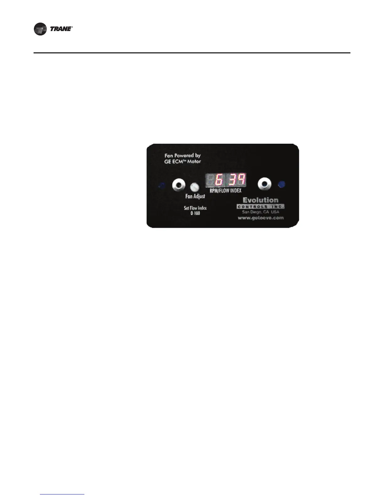
Figure 43. ECM

 Loading...