VAV-SVX01C-EN 71
Troubleshooting
3. Auxiliary sensor wired incorrectly
• Check wiring for the correct connections. See “UCM 4.2 Installation and Wiring,” p. 12 for
further details on Auxiliary sensor wiring.
4. Defective Auxiliary sensor
• Disconnect the zone sensor terminal plug from the UCM and using an Ohmmeter, measure
the resistance across the auxiliary sensor wires. Compare the resistance to temperature
using Table 3, p. 11. The resistance should shown value should be within ± 2 degrees near
those measured with an accurate temperature measuring device. If not, the Auxiliary sensor
needs to be replaced.
5. Defective wiring or UCM
• See if the VAV UCM is outputting 5VDC. This can be done by disconnecting the wires on the
VAV UCM on terminals TB3-5 and TB3-6 and measure the VDC. It should be 5VDC. If the
meter does not read 5VDC at the UCM the wires going to the zone have an open. If 5VDC is
not present check incoming power to the UCM board on TB1-1 and TB1-2. Should measure
24 VAC ± 10%. If proper voltage measured on TB1-1 and TB1-2 and no voltage at TB3-1 and
TB3-2 replace UCM.
Note: If no voltage at TB3-5 and TB3-6 see UCM see UCM failure procedures.
6. More than one UCM connected to a single zone sensor
• Cut jumper wires (W4) on all slave units. If jumper is not cut it will give erroneous
temperature value.
Auxiliary C0
2
Sensor Failure Procedures
In the event that the UCM reports an incorrect or failed Auxiliary C0
2
sensor input temperature,
properly inspect the following:
1. Check configuration of the VAV unit
• Auxiliary sensor needs to be configured as C0
2
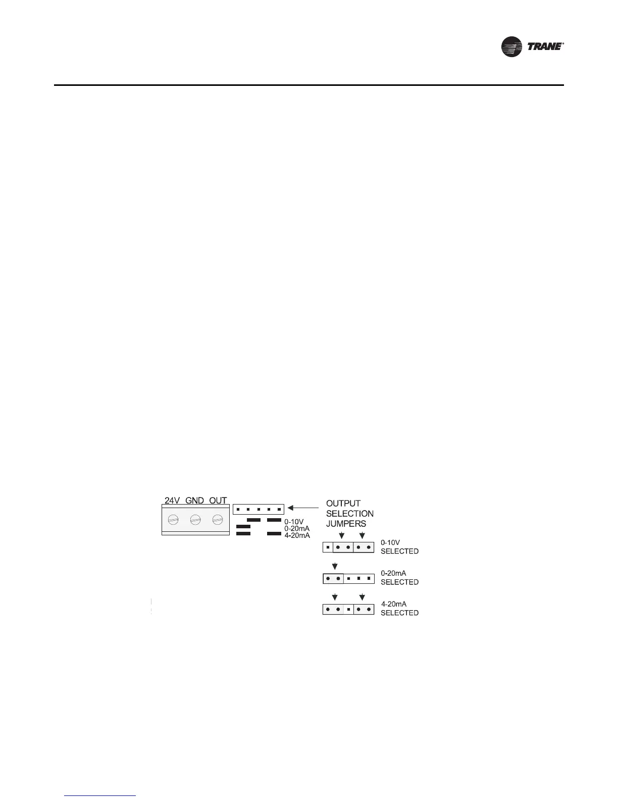
2. Check jumper position on C0
2
sensor
• Needs to be set up as 0-10VDC
• Check voltage between J3-6 and J3-5 with the sensor connected
• Should be between 1-10VDC. If it is not check incoming power
• Check voltage input to C0
2
Sensor with voltmeter
• Voltage needs to be between 20 to 26 VAC; nominal 24 VAC
Figure 41. Jumper position

 Loading...