BAS-SVX04C-EN • Wireless Sensors 35
Maintenance and Troubleshooting
This section describes features of the receiver and sensor that are to be used for
maintenance and troubleshooting.
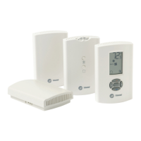
Locations of LEDs, Test button, Test Symbols, and Error Codes
The receiver for all models has four LEDs: LED1, LED2, LED3, and LED5. Figure 9 shows
their locations.
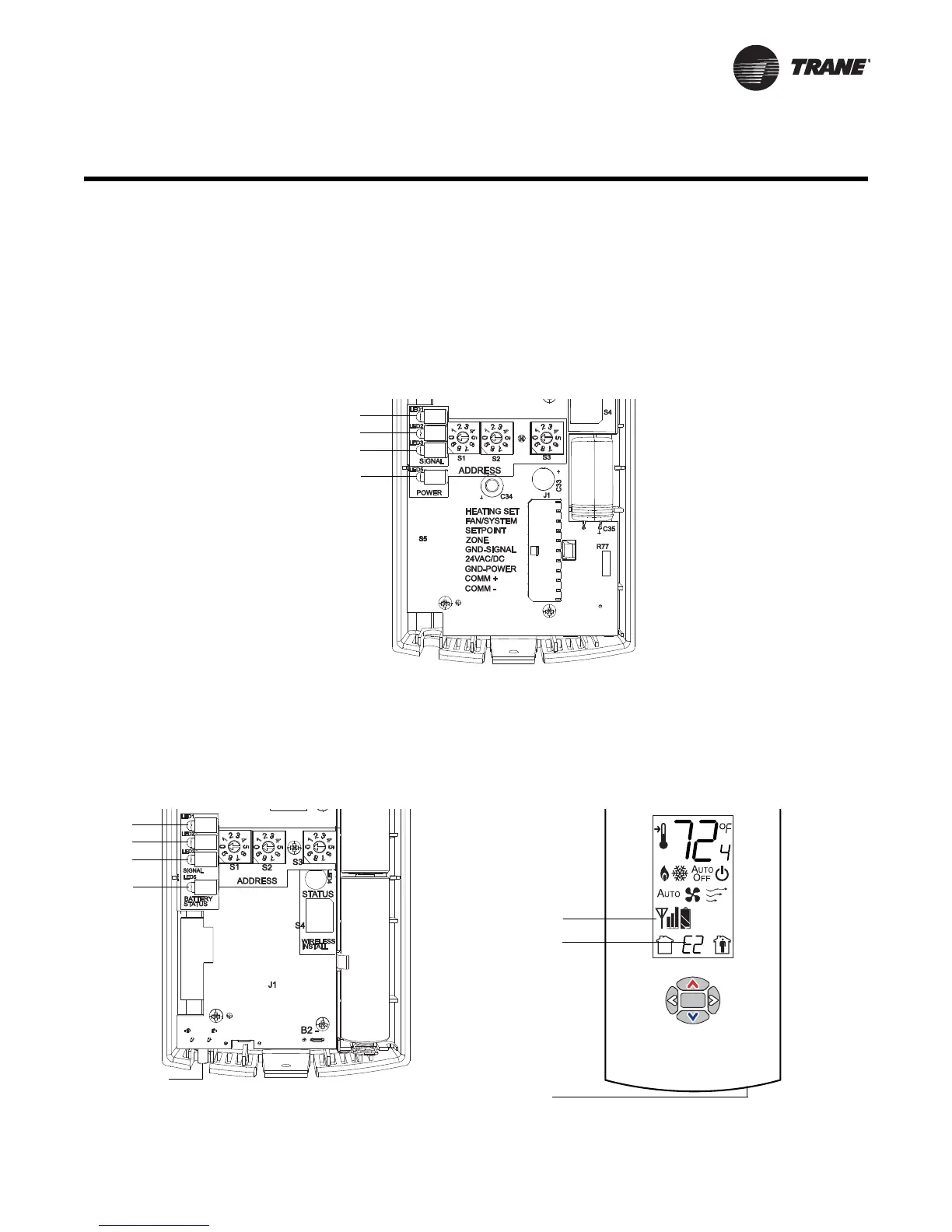
The sensor for models WTS and WZS have four LEDs: LED1, LED2, LED3, and LED5. The
sensor for model WDS has test symbols and error codes that appear on the display. All
three sensor models have a Test button. Figure 10 shows their locations.
Figure 9. LED locations on the receiver
Figure 10. LED, Test button, and symbol locations on the sensor
Test symbols
Error code
Test button
LED1
LED2
LED3
LED5
Test button
WTZ, WZS sensor WDS sensor
 Loading...


