38 Wireless Sensors • BAS-SVX04C-EN
Maintenance and Troubleshooting
Testing Battery Status
Initiate a battery status test as follows:
• On models WTS and WZS, push the Test button on the sensor (see location on
Figure 10, p. 35). LED5 on the sensor responds by indicating the level of battery
strength, as shown in Tab le 6.
• On model WDS, push the Test button on the sensor (see location on Figure 10, p. 35).
In response, a battery test symbol appears on the display. The symbol shown
indicates battery life expectancy (see Table 7, p. 39).
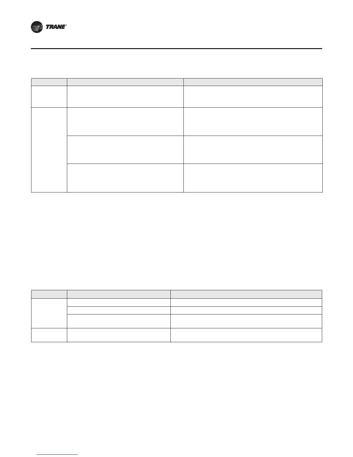
Table 5. Observing signal strength on the receiver
User action LED state (receiver, all models) Indicates...
None LED1: Off
LED2: Off
LED3: Off
Normal state
• No Test button press.
Press Test
button on the
sensor
LED1: On
LED2: On
LED3: On
Displays for 5 seconds, then constantly Off
Excellent signal strength
• Good signal margin for reliable communication.
LED1: Off
LED2: On
LED3: On
Displays for 5 seconds, then constantly Off
Satisfactory signal strength
• Adequate signal strength for reliable communication.
• Moving sensor or receiver may improve signal strength.
• Increased channel switching may reduce battery life.
LED1: Off
LED2: Off
LED3: On
Displays for 5 seconds, then constantly Off
Poor signal strength
• Unreliable communication
• Strongly recommend moving the sensor or receiver to a
better location
Table 6. Battery status: LED5 on model WTS and WZS sensors
User action LED state (WTS, WZS) Indicates...
Press Test
button
Solid green for 5 seconds Battery is adequate for proper operation.
Solid red for 5 seconds 25% battery life left. Batteries should be replaced.
No light Batteries life expired or not installed properly, or sensor is
defective.
None Blinking red: 1-blink pattern
(a)
repeated 5
times. Cycle repeats every 15 minutes.
Approximately 14 days of operation remain before the battery
is too weak to power the sensor.
(a)Blink pattern is On for 1/4 s, Off for 3/4 s, with 2 s Off between repetitions.
 Loading...


