ELECTRICAL SYSTEM
35
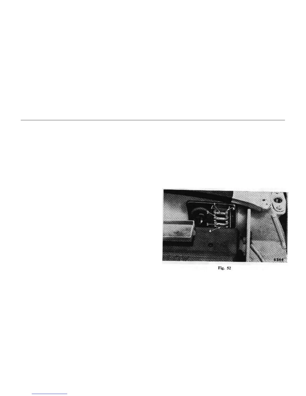
Fuses (Fig. 52)
The fuse assembly, located at the left-hand side of the bulk-
head, houses three 35 amp. operational fuses and two spares at
positions (4)
The top fuse (1) fed by a white cable from the ignition/starter
switch protects the reverse lamp circuit, flasher circuit, heater
circuit (when fitted), fuel and temperature indication circuits,
stop lamp circuit and windscreen wiper circuit.
The middle fuse (2) fed by a red/green cable from the master
light switch protects the front parking lamp circuit and tail lamp
and plate illumination lamp Circuit.
The bottom fuse (3) fed by a brown cable direct from the
battery protects the horn circuit and headlamp flasher circuit.
Failure of a particular fuse is indicated when all circuits
protected by it become inoperative. If a new fuse fails, establish
the cause and rectify the fault before renewing the fuse.
H.T. Cables
All high tension cables fitted to the ignition system are made
from carbon impregnated nylon or cotton cords, encased in
rubber or neoprene to form a high resistive conductor. Replace-
ment cables should be obtained from a Standard/Triumph
Distributor or Dealer and must be of the same length and type as
the originals.

 Loading...