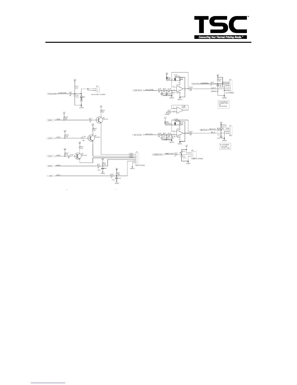
3.5 Sensor&Key
Fig. 3.5 Sensor&Key
JP1 is the connector which connects to the LEDs and Keys. The signal of LED is High when
the LED is bright; otherwise, it is low.
JP2 is the connector of the head open sensor. The Head open sensor is a micro switch. the
voltage is High when the print head open; otherwise, it is low.
The signal of the key is “LOW” when the keys is press; otherwise, t is “HIGH”.
P4 is the connector which connects to the block mark sensor.
The block mark sensor is a reflect in sensor. the block mark sensor signal voltage is “HIGH
“ when the block mark is detected; otherwise, it is “LOW”.
JP5 is the connector which connects to the gap sensor and the gap emitter level. The gap
level is a emitter source intensity control signal. signal. The gap sensor is a penetrable
sensor. the gap sensor signal voltage is low when the gap is detected; otherwise, it is high.
JP7 is the connector of the HEAD-OPEN sensor. When the printhead open,
The HEAD SENS signal is “High” ; When the printhead close, The HEAD SENS Signal
is ”LOW”.
 Loading...