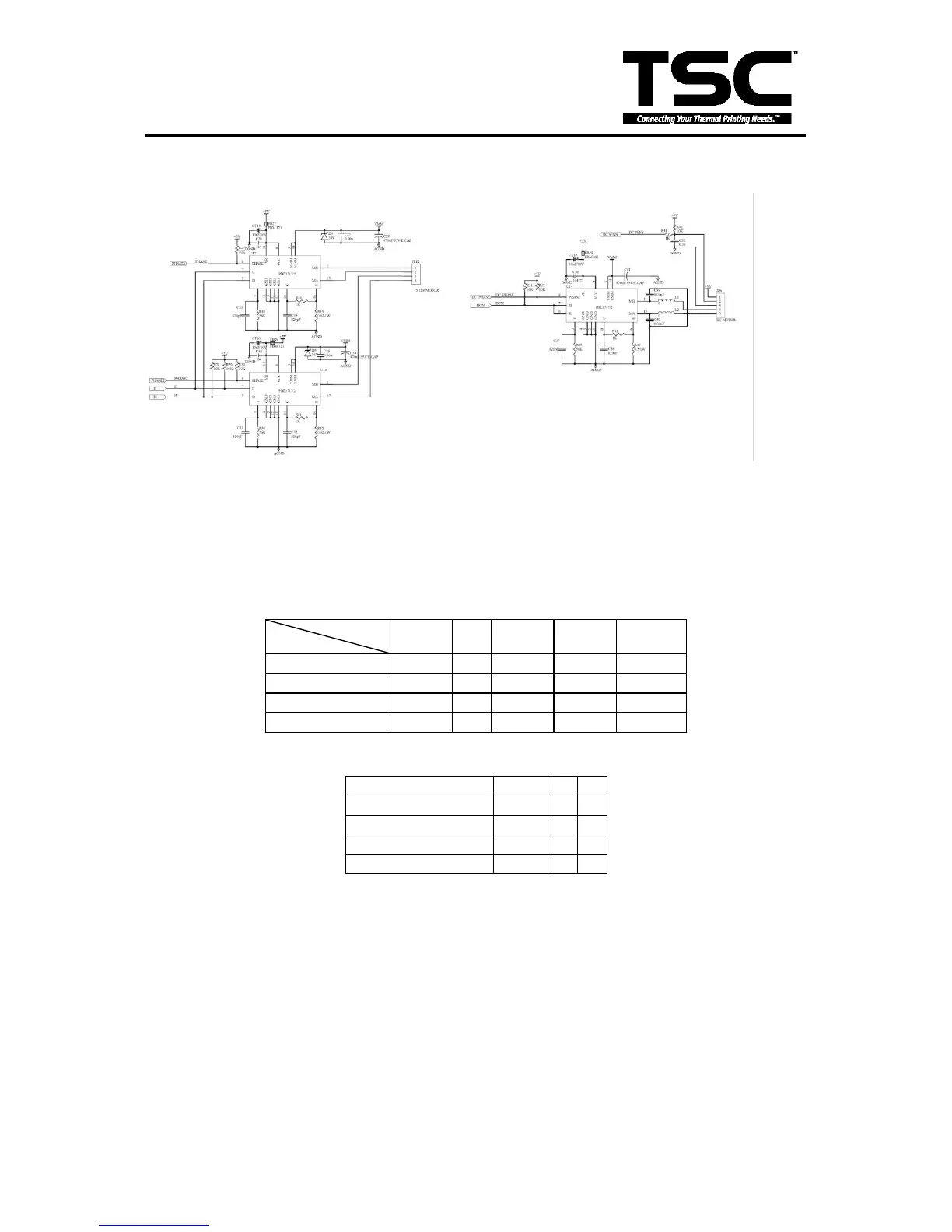
3.10 Stepping Motor And DC Motor Driver/ Protection Circuit
Fig. 3.10 Stepping Motor And DC Motor Driver/ Protection Circuit
This is the Stepping Motor Drive. Connector JP12 sends the pattern as shown in table1. The
status of I0 & I1 determines the stepping motor power level, the power level pattern is
shown in table2. PHASE1 and PHASE2 determine the pattern of stepping motor drive circuit.
For example, the sequence of PHASE1/PHASE2 in full step mode is 0/0 → 0/1 → 1/1 →
1/0.
Table2 Stepping motor power pattern
The power of DC motor is on when DCM pin is at ‟LOW‟ level. DC-PHASE determines the
DC motor run direction (forward or backward).
 Loading...