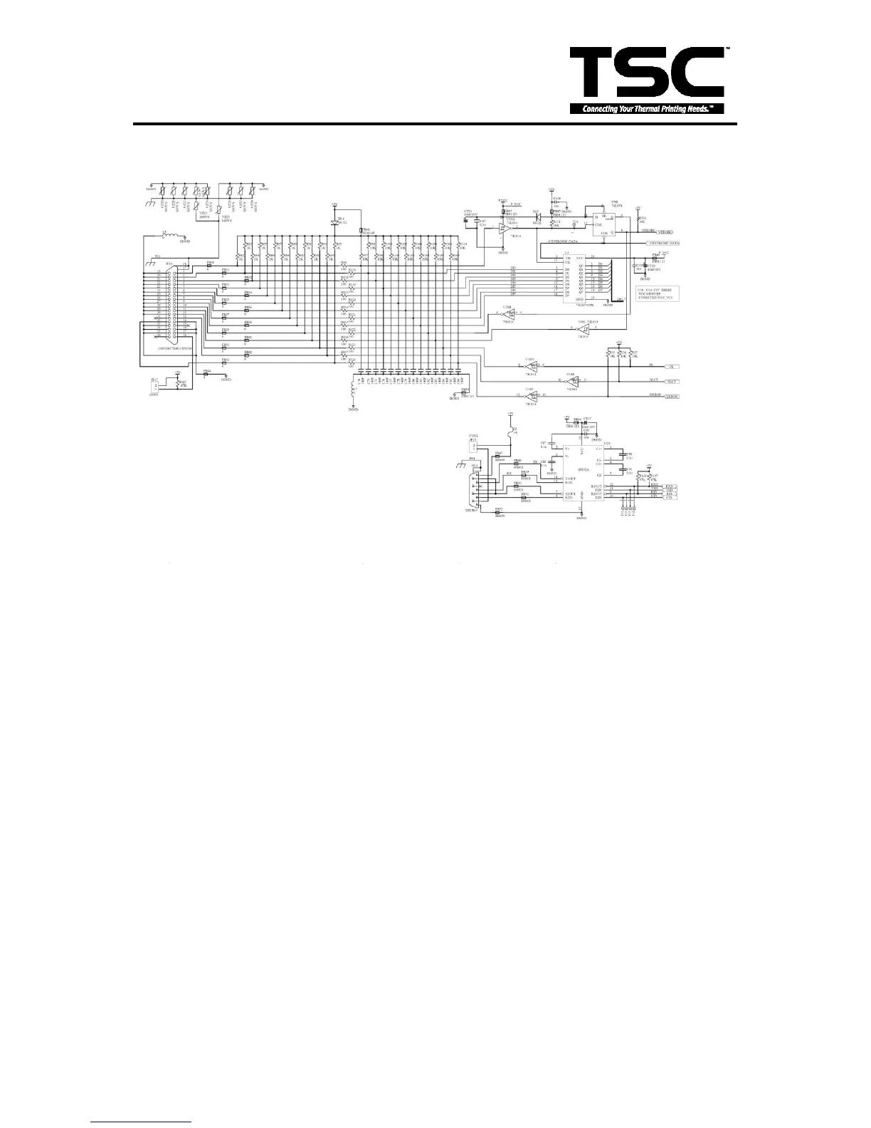
3.11 Communication (Serial & Parallel Port) Circuit
Fig. 3.11 Parallel port and RS-232 Circuit
The RS-232 Circuit is for use with the externally connected personal computer and
keyboard unit. JP13 connects to PC serial port through the RS-232 cable. RxD is the
data receive pin of MCU. CTS is the Clear To Send of MCU, which sends the signal
from the external device. TxD is the data output pin of MCU. RTS is the Request To
Send signal which MCU sends to the external device.
The parallel port circuit is for use with the externally connected personal computer
parallel port through the printer cable. When PC‟s strobe signal comes in, the printer
responds the „busy status‟ until it reads the data from parallel port. Printer will respond
the „error signal‟ to PC when it is in error status.
 Loading...