Part Two
“Check the
Sensor Cable”
flashing on
display.
Verify the sensor cable is correctly plugged into the DIM
and sensor. Connector is polarized but can be forced on
backwards.
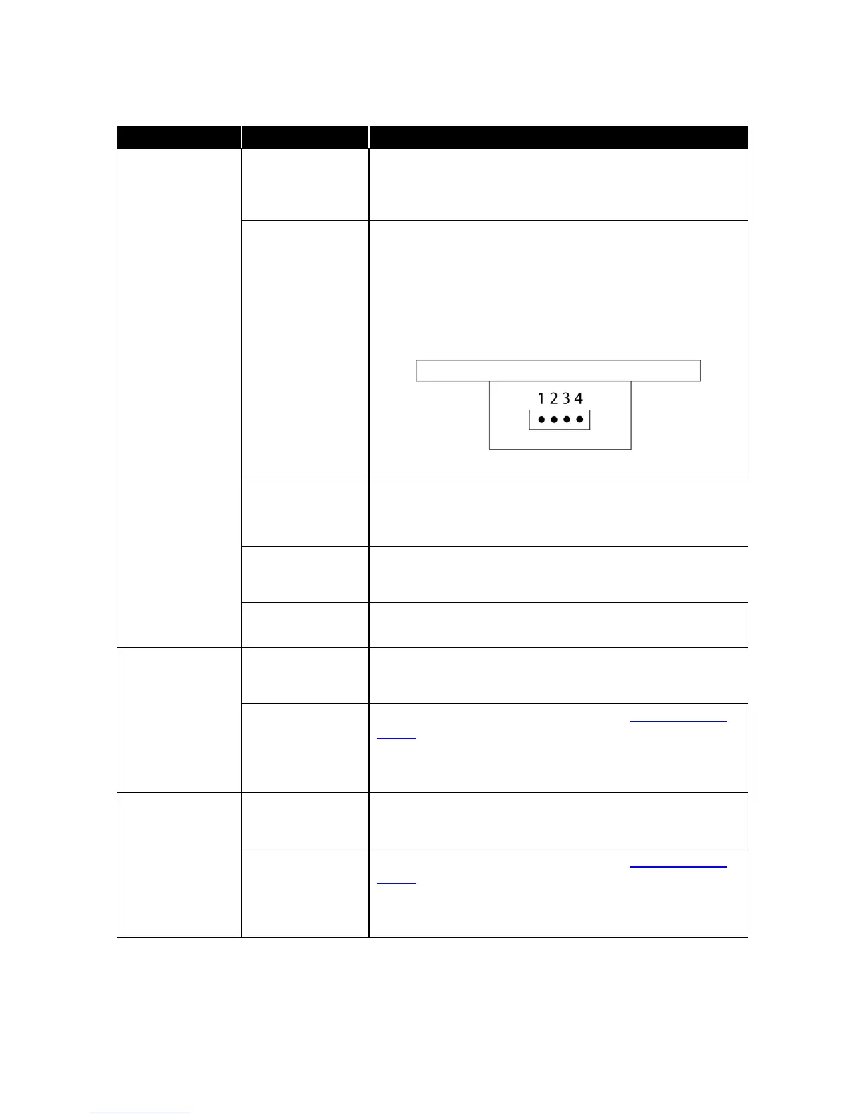
Disconnect the velocity sensor cable from the back of
DIM. Depress the latching piece on the connector to pull it
out. Use an ohm meter to measure the resistance
between the sensor connections indicated in figure below.
The resistance between pins 3 and 4 should be between
10 and 12.5 ohms. The resistance between pins 2 and 4
should be between 120 and 140 ohms. If resistance does
not measure correctly, verify that sensor cable is good.
Figure 6: Velocity Sensor
Verify wire is terminated the same on both ends of cable.
Confirm wire colors match pin 1 to 1, pin 2 to 2, etc. Test
sensor cable with an Ohmmeter to ensure that cable
terminations are good.
Confirm the fume hood face velocity is over 1000 ft/min. If
face velocity exceeds 1,000 ft/min, exhaust system needs
balancing.
Controller not
calibrated.
Remote
emergency does
not work.
Incorrect wiring
or defective
switch.
Disconnect emergency remote wires from DIM. Verify
wiring with an Ohmmeter by switching the emergency
switch open and closed. If operational, reconnect to DIM.
Verify wiring and switch are good. Enter DIAGNOSTICS
menu IN# EMERG PURGE item. Display will indicate
OPEN or CLOSED. Toggle the remote emergency switch,
and the display should change between OPEN and
CLOSED. If no change, replace DIM.
Remote setback
does not work.
Incorrect wiring
or defective
switch.
Disconnect remote wires from DIM. Verify wiring with an
Ohmmeter by switching the setback switch open and
closed. If operational, reconnect to DIM.
Verify wiring and switch are good. Enter DIAGNOSTICS
menu IN# NIGHT SETB item. Display will indicate OPEN
or CLOSED. Toggle the remote setback switch, and
display should change between OPEN and CLOSED. If
no change, replace DIM.
 Loading...