ZED-F9P-Integration Manual
UBX-18010802 - R01
5 Design Page 41 of 64
Objective Specification - Confidential
Pin No Name I/O Description
53 TIMEPULSE O Time pulse
54 Reserved - Reserved
Table 9: ZED-F9P pin assigment
USB is currently only made available for debugging purposes.
5.2 RF front-end circuit options
The first stages of the signal processing chain are crucial to the overall receiver performance. Also,
in many applications an input connector may be used to receive the RF-input. This can provide a
conduction path for harmful or even destructive electrical signals and hence the RF input needs to
be protected accordingly.
If a combined GNSS L1 + L2 + L band (NEO-D9) RF system is to be used, a suitable band power
divider should be used.
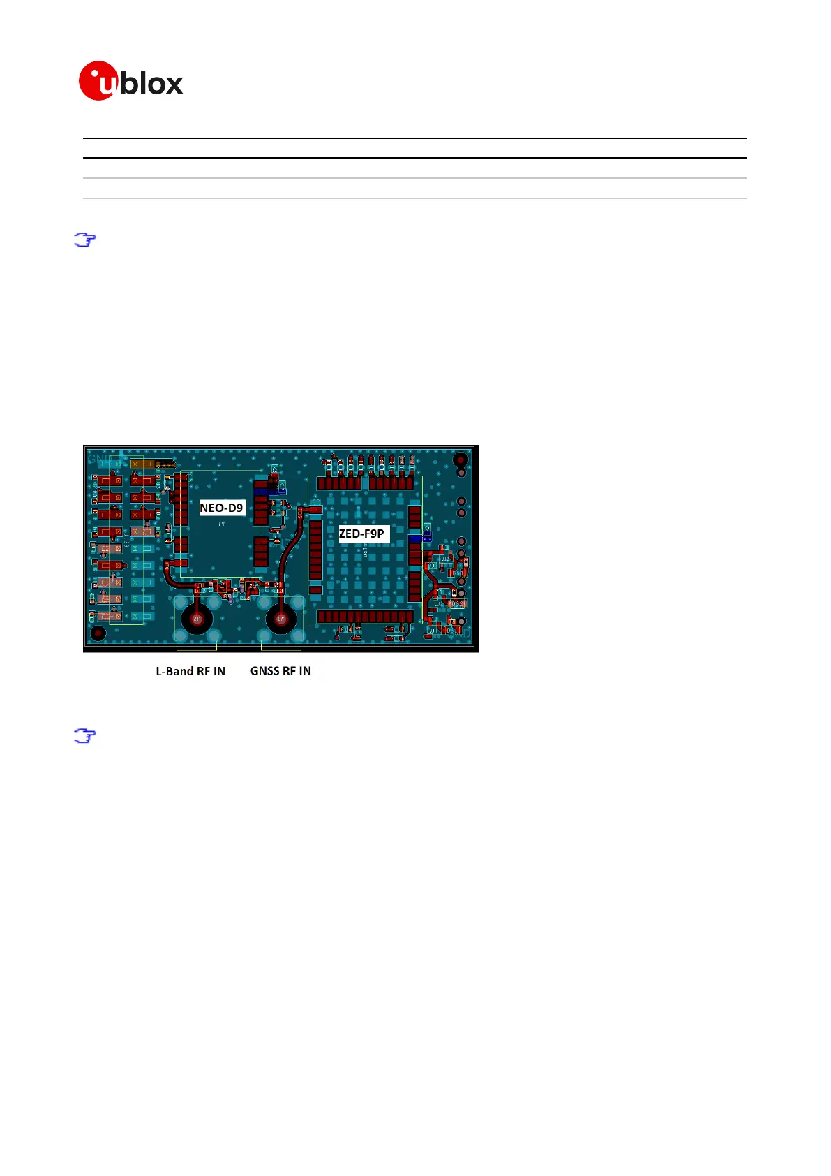
Separate RF IN system
Figure 38: ZED-F9P and NEO-D9 RF IN
For a separate RF IN system the L-Band antenna might be separate from the GNSS antenna.
The L-Band antenna must meet the signal specification for the NEO-D9 module being used.
Combined GNSS and L-Band RF IN
If the antenna is a combined GNSS and L-band corrections unit with a single RF feed there are
several options based on RF competence and operating temperature range of target application.
An equal power splitter can be implemented to split the power and frequency range equally between
the ZED-F9P and the NEO-D9.
This can be achieved by using discrete Power splitter devices that are in a single SMD package.

 Loading...


