ZED-F9P-Integration Manual
UBX-18010802 - R01
7 Antenna Page 60 of 64
Objective Specification - Confidential
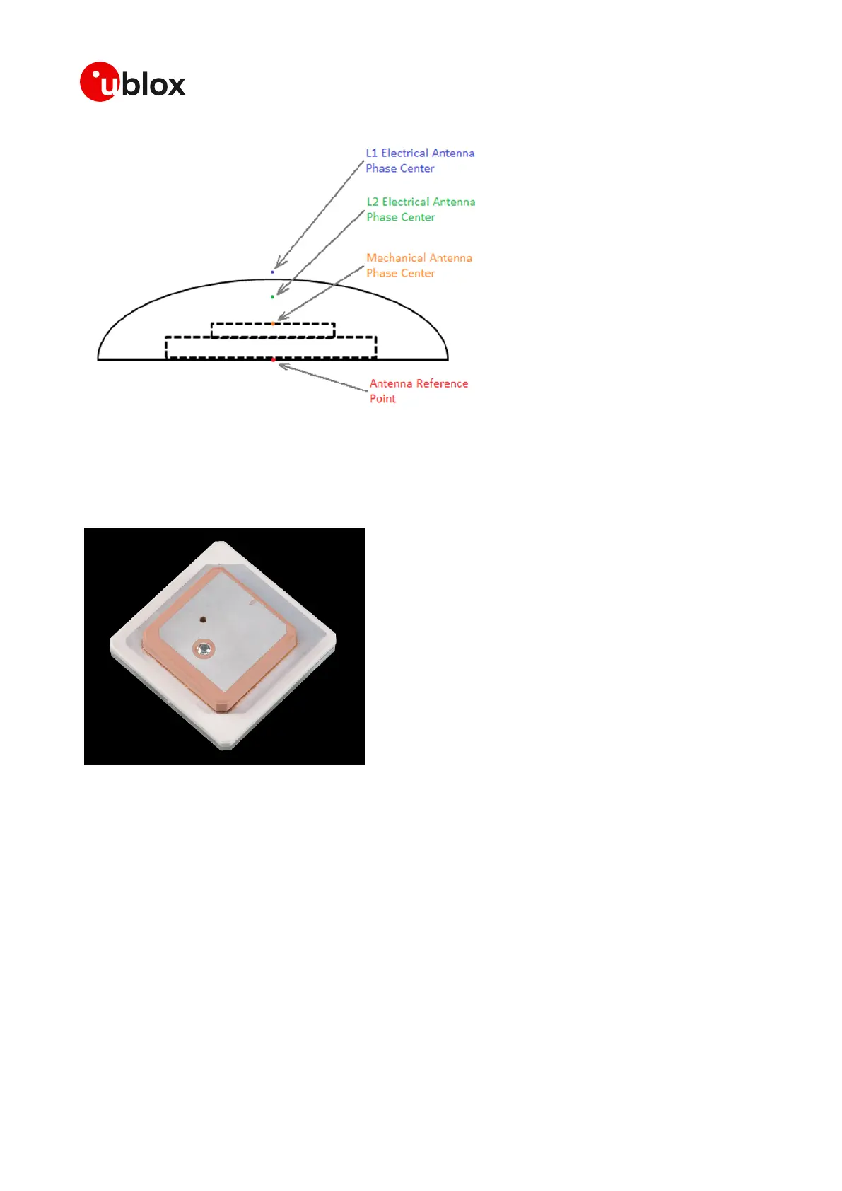
Figure 59: Stacked patch antenna
It is important to note that the absolute position of the antenna placement needs to be calculated
from the L1/L2 phase-variation. The L1 and L2 patch phase centers must vary to a minimum. The
final Antenna Reference point or ARP is what is then used to calculate the actual precise antenna
position.
Figure 60: Ceramic Stack
If the antenna is to be used in an automotive application in mass production. The final placement of
the antenna will affect the Phase center variation, the antenna ground plane size and shape and the
antenna location to other bodies or structures will cause offsets. The final Phase center variation
calibration will need to be done on the final vehicle with the antenna in its final location. If the phase
variation of a specific antenna is repeatable between samples, the Phase center variation can be
calibrated succesfully.
The absolute best performance will be obtained with the antenna in the center of the roof and not
tilted at any large angle. However the placement of automotive antenna in a mass production vehicle
will probably be compromised.
The antenna cannot be placed under a dashboard, in a rear view mirror or on the rear parcel shelf. It
needs to have very good signal levels and the wide as possible view of the sky.
Low cost L1 + L2 stacked patch antenna must have a minimum band pass performance from their
patch elements and the required internal SAW filtering. An example of the actual measured Band
pass characteristics of a low cost L1 + L2 antenna is shown below.

 Loading...


