Measurement Operation(16)
2.Set the rotary switch of the multimeter to the 200mV
or 2VDC. As prompted at the LCD connect terminal,
insert the red test lead into the V terminal and the
black one into the COM terminal.
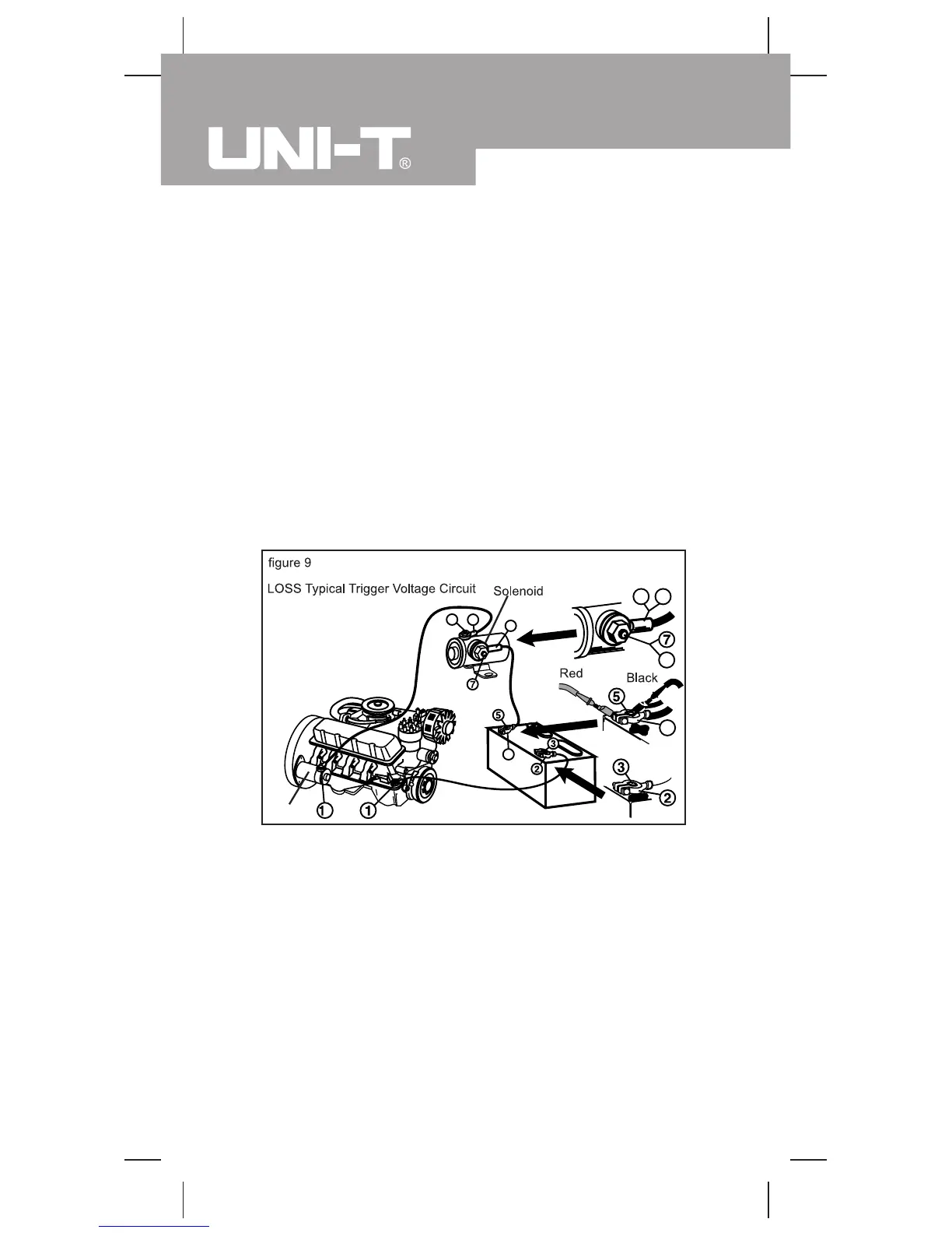
3.Refer to the LOSS typical trigger voltage circuit.
(See the details in figure 9)
Test the voltage between any of the following pairs of
points respectively:1&2, 2&3, 4&5, 5&6, 6&7, 7&8, 8&
9, 8&10
Component Voltage
Switch 300 mV
Lead 200 mV
Grounding 100 mV
Battery Lead Connector 50 mV
Wiring 0.0 V
Compare the readings of the tested voltages against the
said table. If the voltage is on the high side, check the
components and connectors to see if there is anything
wrong. If anything wrong is found, do necessary servicing.
Starter
Model UT105: OPERATING MANUAL
32

 Loading...