Model UT105: OPERATING MANUAL
38
Measurement Operation(22)
The functions of a magnetic resistance sensor is similar
to those of a Hall sensor and the testing methods of both
sensors are also similar. Their normal resistance is
generally in a range of 150Ω to 1 kΩ. Refer to the ranges
of resistance in various kinds of automotive manuals for
the details.
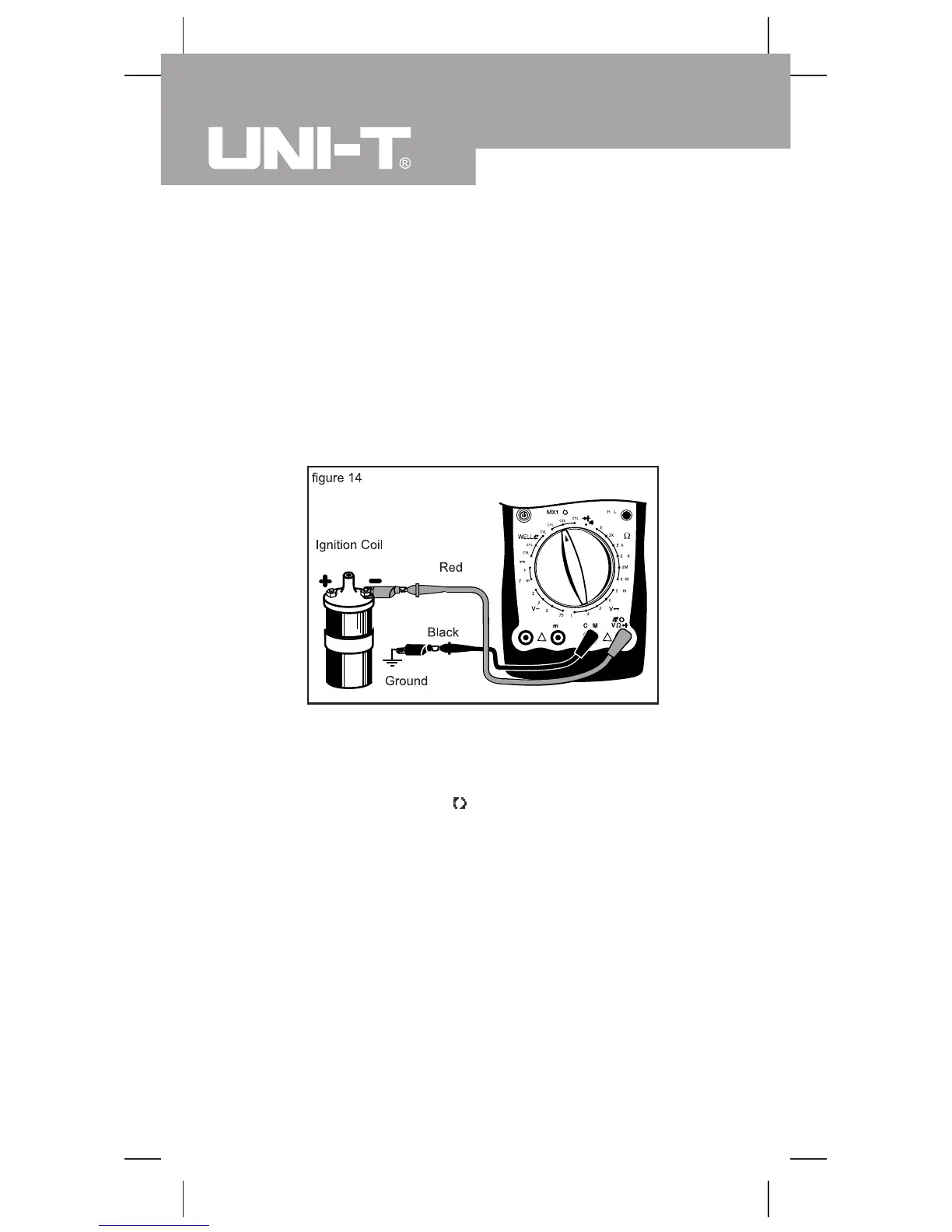
5.RPMx10 Testing (see figure 14)
(1) Set the rotary switch to RPMx10 and select the number
of cylinders in the automobile to be tested.
(2) As prompted at the LCD connect terminal, insert the
red test lead into the terminal and the black one
into the COM terminal.
(3) Connect the black test lead probe to the ground (i.e.
ground strap connection) of the automobile and the
red one to: the appropriate testing test terminal of
the computer of the automobile if the automobile is
in a DIS type (Refer to the servicing handbooks of
various kinds of automotive manuals for the detailed
position); or the negative pole of the ignition coil if the
automobile is equipped with a distributor board (Refer
to the servicing handbooks of various kinds of
automotive manuals for the detailed position).

 Loading...