Model UT105: OPERATING MANUAL
37
Measurement Operation(21)
(1) Move the Hall sensor out of the automobile and see
the details of the operation in various kinds of automotive
manuals.
(2) Connect the positive pole of the 9 V battery to the
source end of the sensor and the negative pole to the
ground end of the sensor by referring the details to
the positions of the source and ground ends of the
sensor in various kinds of automotive manuals.
(3) Set the rotary switch of the meter to 200Ω . As prompted
at the LCD connect terminal, insert the red test lead
into the Ω terminal and the black one into the COM
terminal.
(4) Connect the red and black test lead probes in parallel
to the signal connect terminal and ground end of the
sensor and the Meter should display a small ohm value.
(5) When a metal plate (blade, steel tape, etc.) is inserted
into a concave magnetic pole of the sensor, the display
of the meter will be enlarged or overloaded; if the metal
plate is moved away, the display will become smaller,
which proves that the sensor is satisfactory.
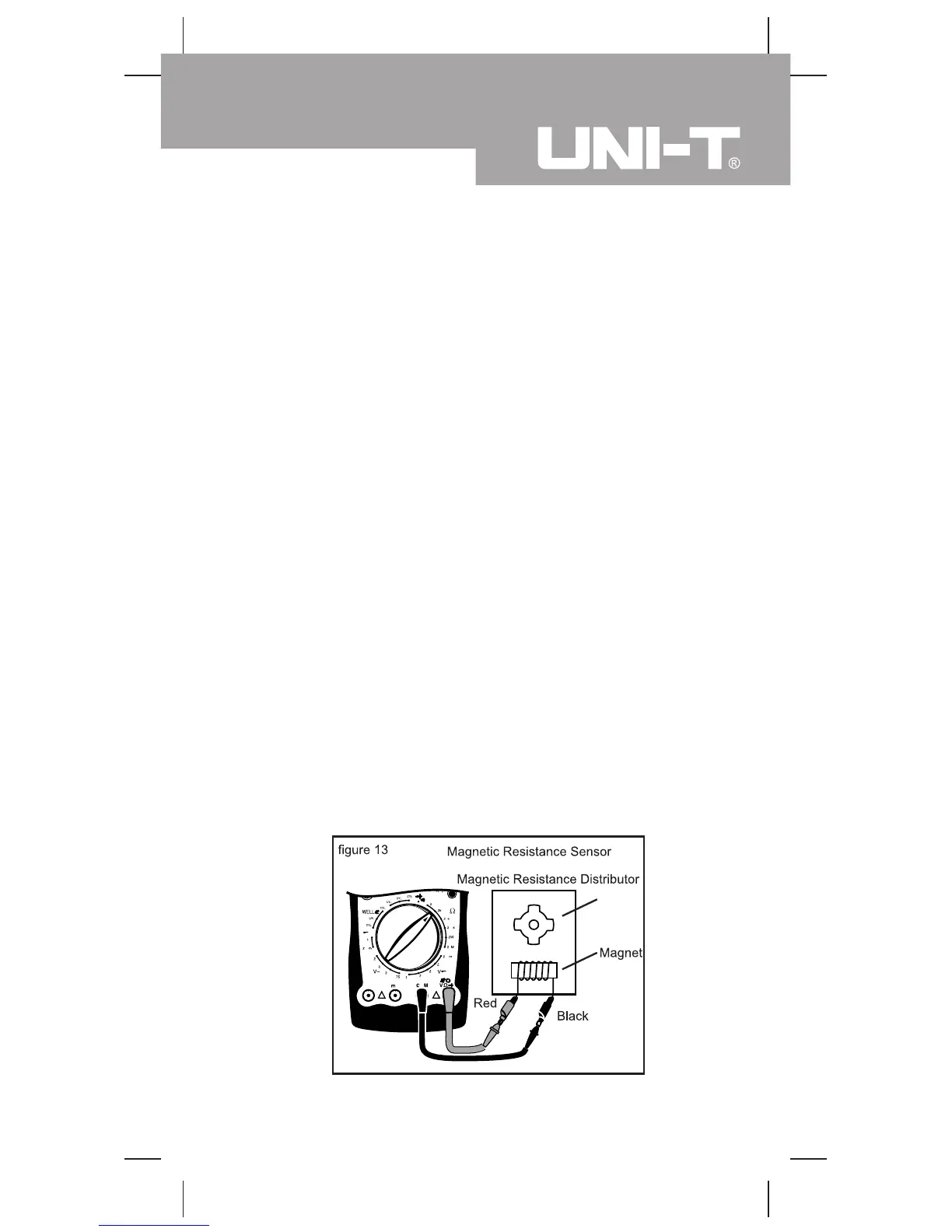
4.Magnetic Resistance Sensor (see figure 13)

 Loading...