Model UT105: OPERATING MANUAL
34
Measurement Operation(18)
I.Ignition System Testing
1.Ignition Coil Testing
(1) Before the operation, cool the engine and cut off the
ignition coil.
(2) Set the rotary switch of the meter to the 200Ω . As
prompted at the LCD connect terminal, insert the red
test lead into the Ω terminal and the black one into the
COM terminal. Test the primary coil of the ignition coil.
(3) Short circuit the red and black test lead probes. Their
short circuit resistance should be less than 0.5Ω. If it is
more, check the test lead to see if it is loose or damaged.
If it is damaged, replace it with a new one.
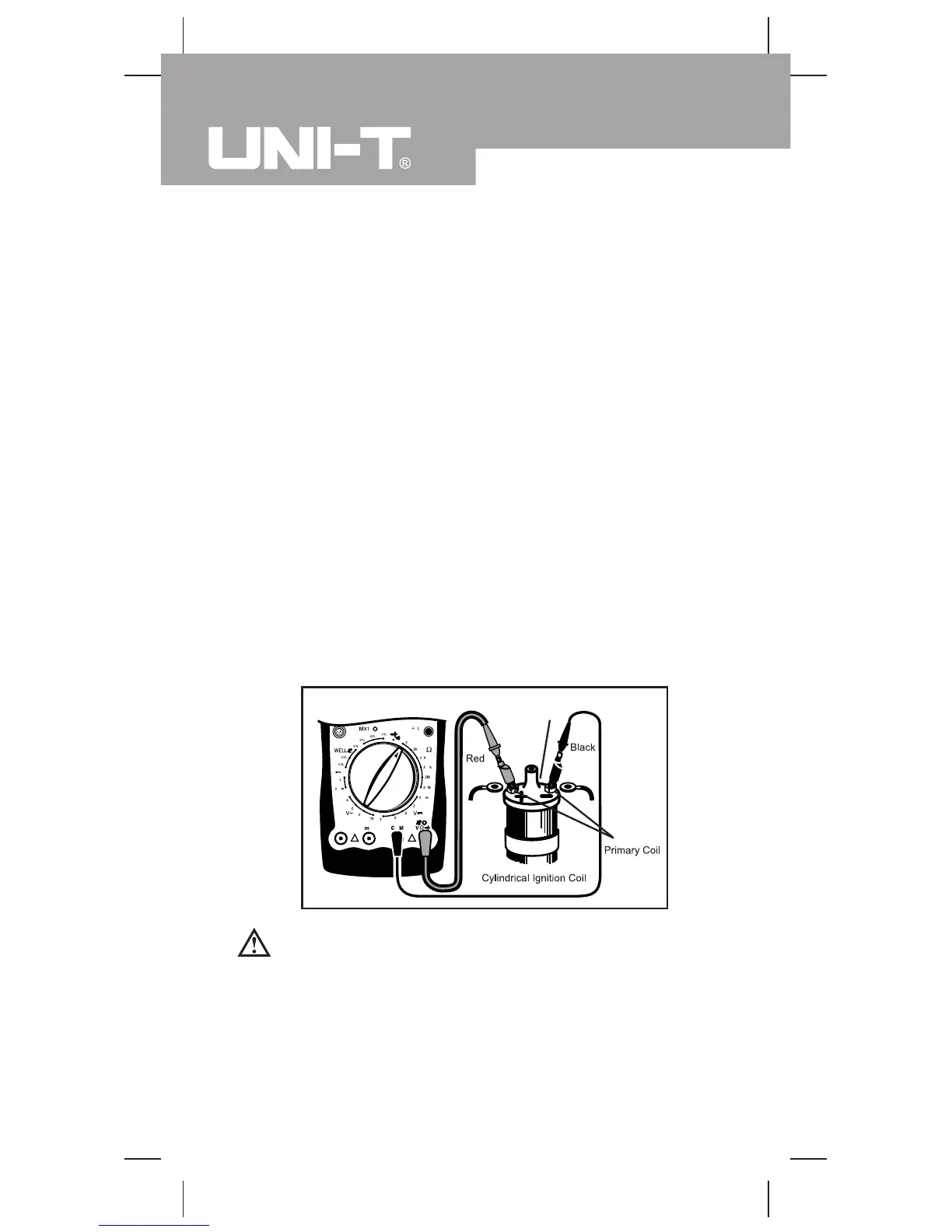
(4) Connect the red test lead probe to the primary “+” pole
of the ignition coil and the black one to the primary “-”
pole of the coil. (see figure 10.) See the detailed positions
in various kinds of automotive manuals.
Secondary Coil
figure 10
Warning:
l The reading of the testing becomes the actual tested
resistance only after the reduction of the short-
circuit values of the test leads.
l The primary resistance is generally between 0.3Ω
and 2.0Ω .

 Loading...