To avoid damages to the Meter or to the devices under test,
disconnect circuit power and discharge all the high-voltage
Warning
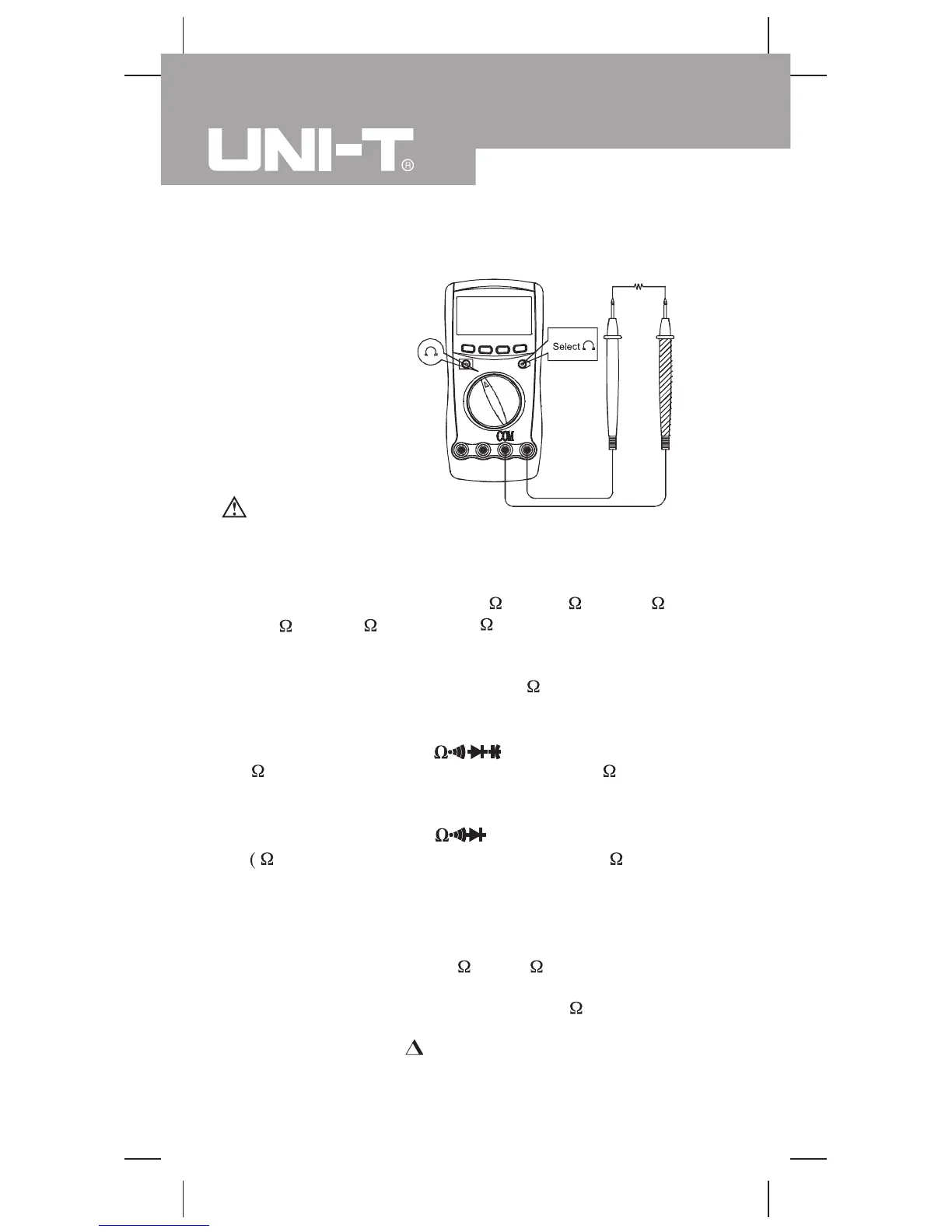
C.Measuring Resistance
(see figure 5)
Measurement Operation (3)
(figure 5)
from the reading.
Set the rotary switch to , resistance measurement
) is default or pressBLUE
The resistance ranges are: 400.0 , 4.000k , 40.00k,
400.0k
, 4.000M
and 40.00M
. To measure resistance,
connect the Meter as follows:
1. Insert the red test lead into theHzV
terminal and the black
test lead into theCOM terminal.
2. Model UT60C/UT60E:
Set the rotary switch to
;
resistance measurement
( ) is default or press
BLUE
button to select measurement
mode.
Model UT60B:
button to select
measurement mode.
3. Connect the test leads across with the object being measured.
The measured value shows on the display.
16
capacitors before measuring resistance.
Note
l The test leads can add 0.1 to 0.2 of error to resistance
measurement. To obtain precision readings in low-resistance
measurement, that is the range of 400.0 , short-circuit the
input terminals beforehand, using the relative measurement
function button
REL
to
measured when the testing leads are short-circuited
automatically subtract the value
Model UT60B/C/E: OPERATING MANUAL
 Loading...