2 Notes on the documentation
14 Installation instructions Heat pump control interface module 0020291573_00
2 Notes on the documentation
▶ Always observe all the operating and installation instruc-
tions included with the system components.
▶ Pass these instructions and all other applicable docu-
ments on to the end user.
These instructions apply only to:
Product
VWZ AI
2.1 Further information
▶ Scan the displayed code using your smartphone in order
to view further information about the installation.
◁ You are guided to installation videos.
3 Product overview
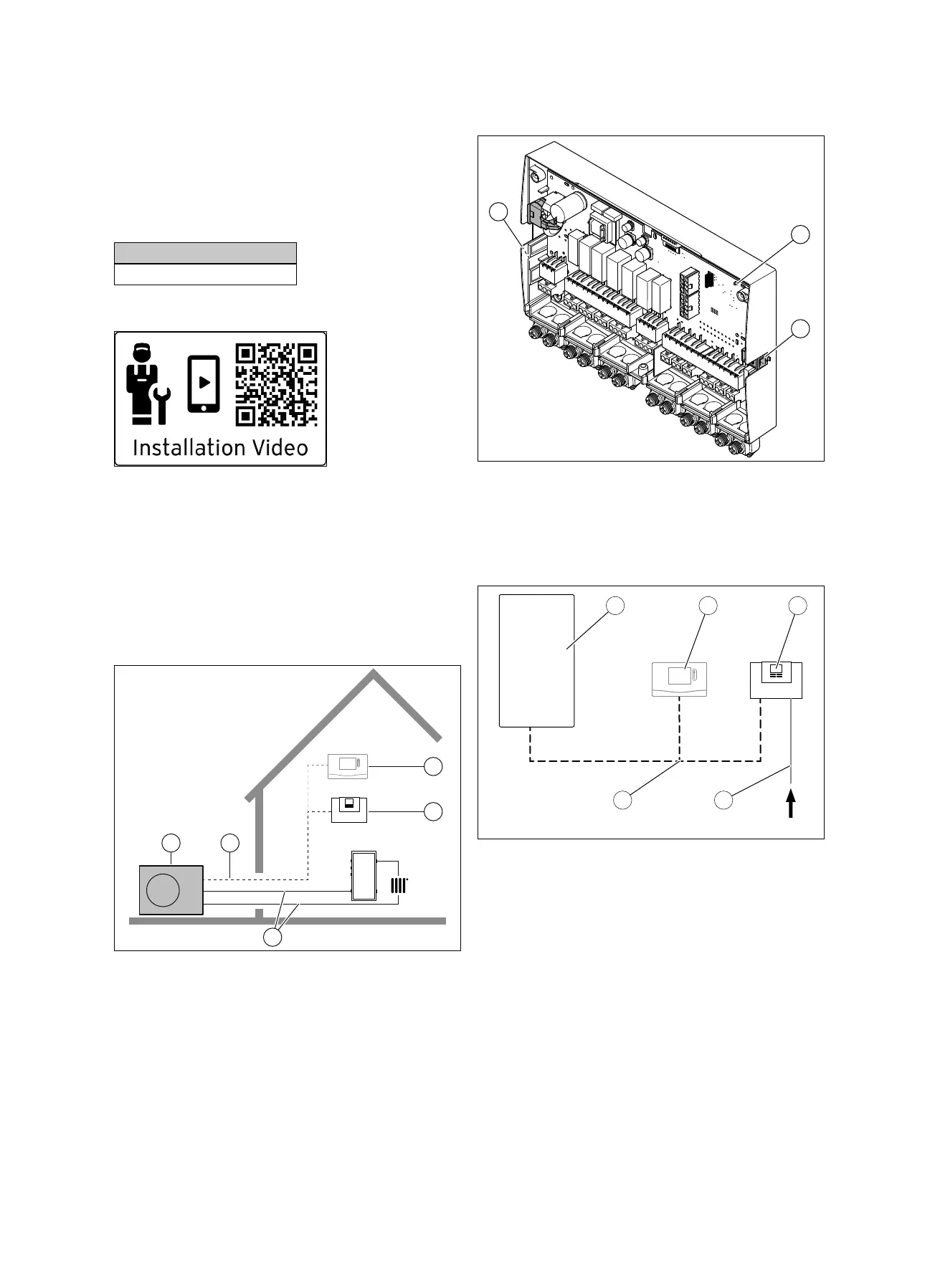
3.1 Heat pump system
Design of a sample heat pump system with monoblock tech-
nology:
1 Heat pump, outdoor unit
2 eBUS line
3 System control (op-
tional)
4 Heat pump control
module
5 Heating circuit
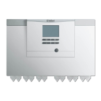
3.2 Overview of functional elements
1 LED
2 Diagnostic socket (for
later use)
3 Identification plate
3.3 Connecting the power supply cable and
eBUS cable in the system
1 Heat pump
2 System control
3 VWZ AI
4 230 V power supply
cable (on-site)
5 eBUS cable
The product is connected to the power supply on-site. You
can branch the eBUS connection to the product at any part
of the eBUS system.

 Loading...