2 Notes on the documentation
4 Operating instructions Heat pump control interface module 0020291573_00
2 Notes on the documentation
▶ Always observe all operating instructions that are en-
closed with the installation components.
▶ Store these instructions and all other applicable docu-
ments for further use.
These instructions apply only to:
Product
VWZ AI
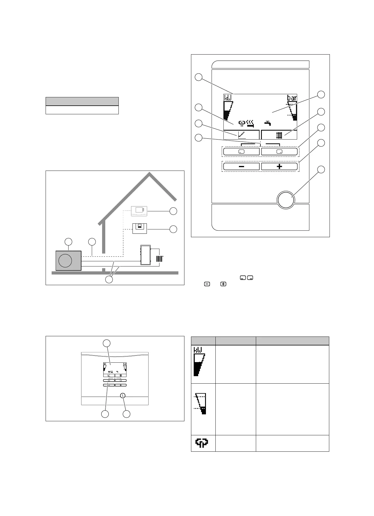
3 Product description
3.1 Heat pump system
Design of a sample heat pump system with monoblock tech-
nology:
1 Heat pump, outdoor unit
2 eBUS line
3 System control (op-
tional)
4 Heat pump control
module
5 Heating circuit
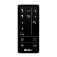
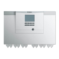
3.2 Control elements
1 Reset button
2 Control elements
3 Display
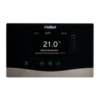
3.3 Control panel
1 Displays the daily envir-
onmental energy yield
2 Display of the current
assignment of the right-
hand selection button
3 Left- and right-hand
selection buttons
4 and button
5 Reset button, restart the
product
6 Access to the menu for
additional information
7 Display of the current
assignment of the left-
hand selection button
8 Displays the symbols
for the heat pump's
current operating mode
9 Display
3.4 Description of the symbols
If you do not press any buttons within one minute, the light
goes out.
Symbol Meaning Explanation
Compressor
power
– Not filled: Compressor not in
operation
– Partially filled: Compressor in
operation. Partial load mode.
– Fully filled: Compressor in
operation. Full load mode.
Filling pressure
in the building
circuit (measured
in the outdoor
unit)
The dashed lines show the
permitted range.
– Displayed statically: Filling
pressure in the permitted
range
– Displayed flashing: Filling
pressure outside of the
permitted range
Noise reduction
mode
– Operation with reduced
sound emissions

 Loading...