Appendix
0020291573_00 Heat pump control interface module Installation instructions 23
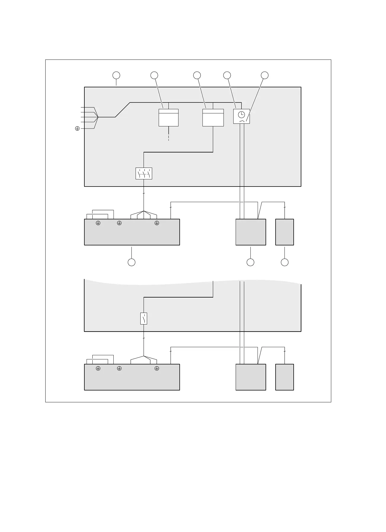
B Basic connection diagram for the energy supply company lockout
3~/400V
1~/230V
BUSEVU BUSL1 L2 L3 NLN
X200
BUS
X206X210
LN
X211
kWh
2
2
N
L1
L2
L3
5
BUSEVU BUSL1 L2 L3 NL N
X200
BUS
X206X210
LN
X211
2
2
3
kWh
1 3 4
5
678
2
1 Meter/fuse box
2 Household electricity meter
3 Heat pump electricity meter
4 Ripple control receiver
5 Potential-free normally open contact, for actuating
ESCO, for the energy supply company lockout func-
tion
6 System control
7 Heat pump control module, PCB
8 Outdoor unit, PCB INSTALLER BOARD

 Loading...