Val Controls A/S • Limfjordsvej 3 • DK-6715 Esbjerg N • Tel. +45 7547 0600 • Fax +45 7547 0611
vc@valcontrols.com • www.valcontrols.com
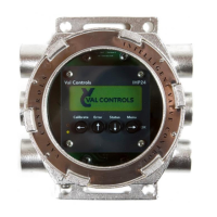
4.4 Indicator, calibration button and USB
All configuration and control must be done through ValConnect.
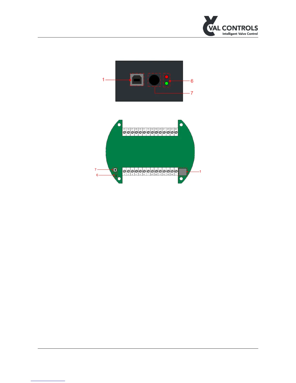
Figure 7: Type A and B interface
Figure 8: Type F interface
4.5 Components
1) USB connector
2) Display
3) Keyboard
4) MT control sensors
5) Status indicators
6) Indicator
7) Calibration button
8) TTL connector
4.5.1 USB connector
The USB connection can be used to connect the IHP to a PC with ValConnect installed.
ValConnect can be used to configure and control the IHP from the PC.
4.5.2 Display
The display is a four lined graphical display with backlight feature and adjustable contrast.
 Loading...