Installation, Operating & Maintenance Instructions
Series 650, DN 100 – 250 (I.D. 4" - 10")
VAT Vakuumventile AG, CH-9469 Haag, Switzerland
Tel ++41 81 771 61 61 Fax ++41 81 771 48 30 Email reception@vat.ch www.vatvalve.com
258550EE
2007-05-11
21/51
3.6 Setup procedure
To enable this valve for pressure control setup steps 1 to 5 must
be performed.
In case position control is required only it’s sufficient to perform steps 1 to 3.
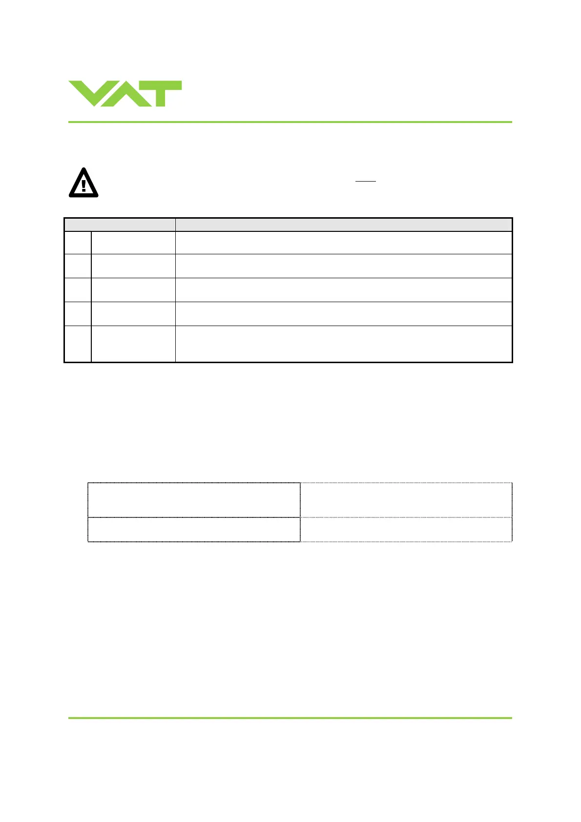
Setup step Description
1
Power up
Turn on external + 24VDC power supply (and external ±15 VDC for sensor power
supply if required). Refer to chapter «3.3 Behavior during power up» for details.
2
Interface
configuration
Functionality of multi purpose digital inputs and outputs must be configured.
Refer to chapter «3.6.1 Interface configuration» for details.
3
Valve and sensor
configuration
Basic configurations of the valve must be adapted according to application needs.
Refer to chapter «3.6.2 Valve and sensor configuration» for details.
4
ZERO
Compensation of the sensor offset voltage.
Refer to chapter «3.6.3 ZERO» for details.
5
LEARN
Determination of the vacuum system characteristic to accommodate the PID
controller. Refer to chapter «3.6.4 LEARN» for details.
Note: Without LEARN the valve is not able to run pressure control
3.6.1 Interface configuration
Interface configuration must be adapted according to application needs.
• Functionality of digital inputs CLOSE VALVE and OPEN VALVE must be selected.
These may be configured as ‘not inverted‘ or ‘inverted‘. Default is ‘not inverted‘.
• LEARN range configuration for remote operation must be selected.
This may either be ‘full range’ or pressure limit according of analog SETPOINT input. Default is ‘full range‘.
Local operation:
(‘Control View’ resp. ‘Control Performance Analyzer’)
Remote operation:
Do configuration in menu ‘Setup / Interface’.
Note: It’s not possible to do interface configuration
via remote operation.
 Loading...


